
Card connector with a slider braking unit

a technology of braking unit and slider, which is applied in the direction of coupling device connection, coupling device part engagement/disengagement, two-part coupling device, etc., can solve the problem of reducing the above-described binding force, the slider cannot be made excessively strong, and the slider speed can be sufficiently reduced. the effect of inertial force applied to the card

Inactive Publication Date: 2008-07-31
FUJITSU COMPONENENT LTD
View PDF6 Cites 12 Cited by
  • Summary
  • Abstract
  • Description
  • Claims
  • Application Information

AI Technical Summary

Benefits of technology

[0017]According to one embodiment of the present invention, a braking force applied to a slider by a slider braking unit is not of a constant level but increases as the slider moves. Therefore, the speed of the slider can be sufficiently decreased by the time the slider reaches a final position. Accordingly, when the slider reaches the final position and stops, the inertial force applied to a card can be reduced so that the inertial force does not exceed a binding force engaging the card with the slider. Consequently, it is possible to prevent the card from springing outside through the card insertion slot.

Problems solved by technology

Furthermore, compact memory cards are small, with each side being only approximately 10 mm, and may thus be difficult to handle for some users.
Because the compact memory card is small and thin, the binding (engaging) force between slider and the compact memory card cannot be made excessively strong.
Furthermore, when abrasion progresses as the memory card is repeatedly inserted and ejected many times, the above-described binding force decreases.
However, in the compact memory card connector described in Japanese Laid-Open Patent Application No. 2005-268089, the braking force applied to the slider is strong at first but weak toward the end.
Therefore, the slider cannot be sufficiently decelerated at the final stage of sliding, and the memory card cannot be reliably prevented from springing out.
Accordingly, it is difficult to apply a braking force to the slider.
Therefore, the slider cannot be sufficiently decelerated at the final stage of sliding, and the memory card cannot be thoroughly prevented from springing out.
Moreover, the built-in roller is a separate component from the slider, which makes it difficult to fabricate this type of connector.

Method used


Image

  • Card connector with a slider braking unit
  • Card connector with a slider braking unit
  • Card connector with a slider braking unit

Examples


Embodiment Construction

[0032]A description is given, with reference to the accompanying drawings, of an embodiment of the present invention.

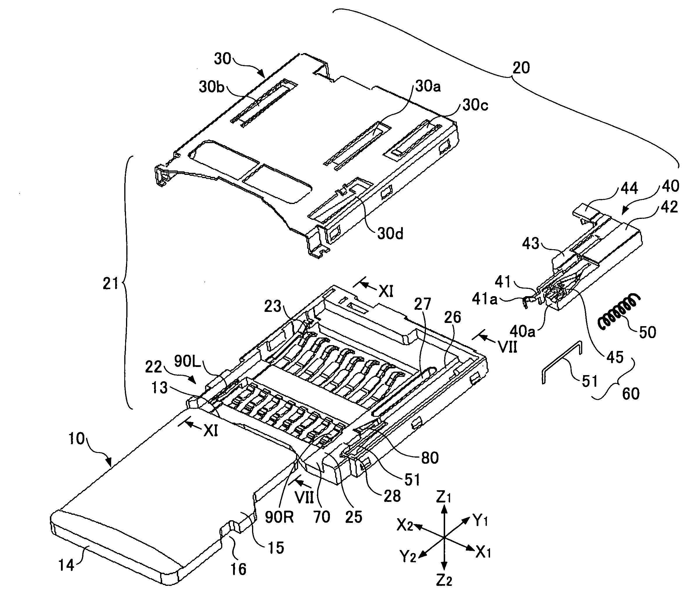
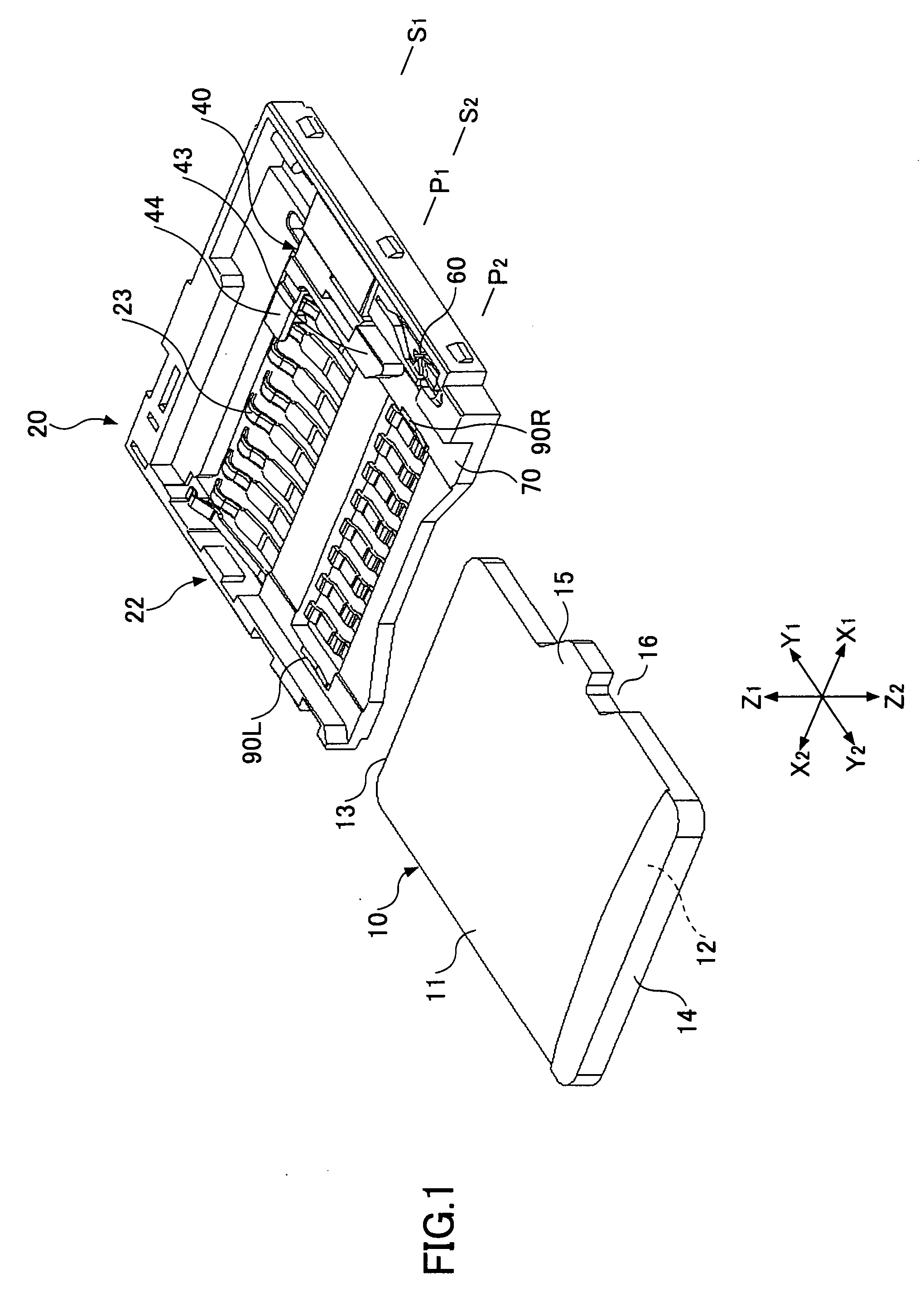
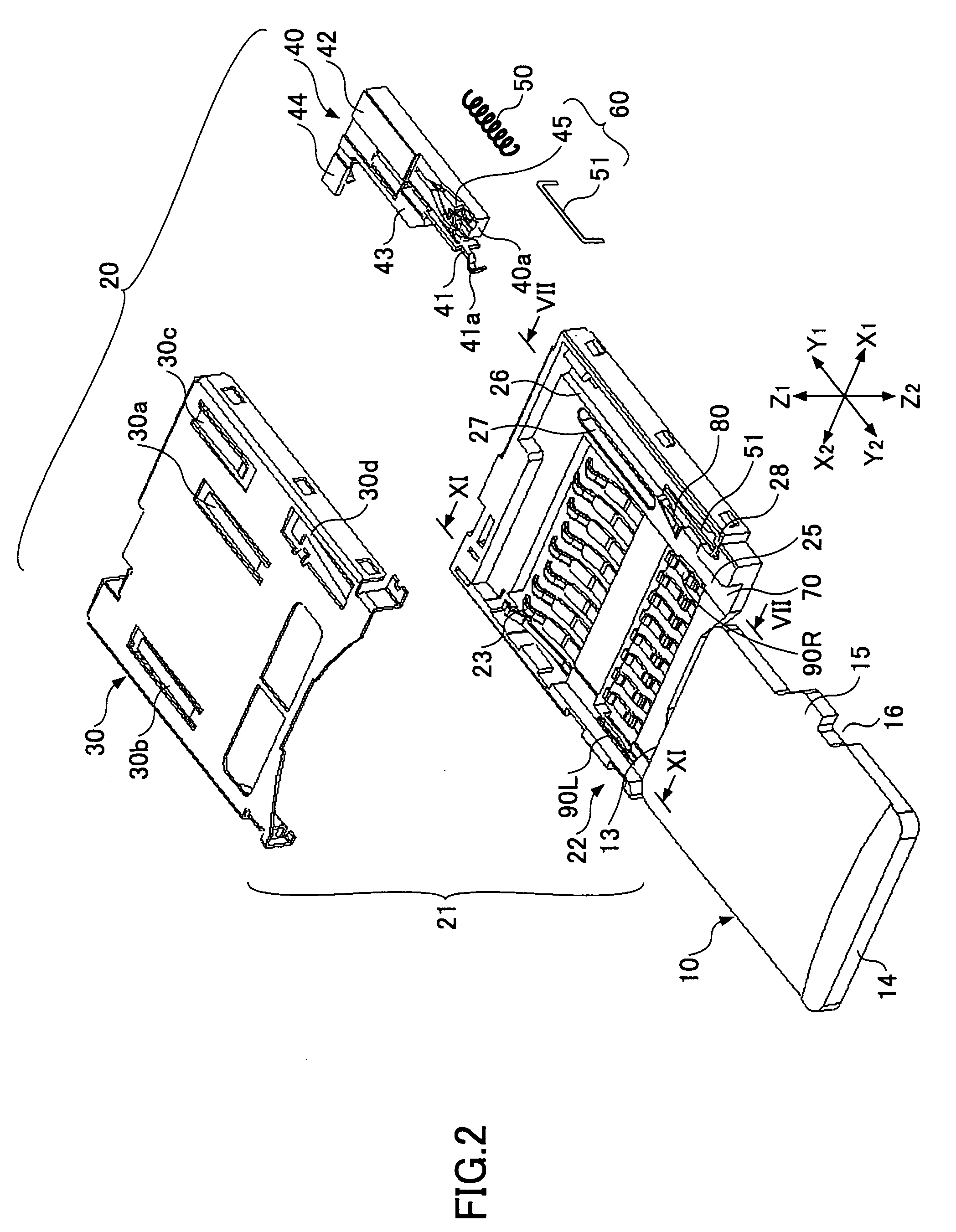
[0033]FIG. 1 is a perspective view of a card connector 20 according to an embodiment of the present invention and a micro SD card 10 (registered trademark, hereinafter “card”). The card connector 20 is shown without its cover and is used for inserting the card 10. FIG. 2 is an exploded perspective view of the card connector 20. In the figures, X1-X2 indicates the width direction, Y1-Y2 indicates the length direction, and Z1-Z2 indicates the thickness (height) direction. The card 10 is inserted in the Y1 direction and ejected in the Y2 direction. The Y1 edge of the card 10 is its front edge and the Y2 edge is its rear edge.

[0034]The card 10 has a top face 11, a bottom face 12, a front edge 13, and a rear edge 14. An IC memory is provided inside the card 10. There are pads (not shown) arranged on the bottom face 12 near the front edge 13. On the X1 edge, there is a prot...


PUM


Abstract

A disclosed card connector includes a housing main unit including a card insertion slot through which a card is inserted into the housing main unit in a predetermined direction; a slider attached to the housing main unit in such a manner as to be slidable along the predetermined direction, wherein the card inserted into the housing main unit is ejected by moving together with the slider as a spring force moves the slider from a position away from the card insertion slot toward the card insertion slot; and a slider braking unit configured to apply a braking force to the slider in such a manner that the braking force increases as the slider moves toward the card insertion slot.

Description

CROSS-REFERENCE TO RELATED APPLICATIONS[0001]The present application is based on Japanese Priority Patent Application No. 2007-015039, filed on Jan. 25, 2007, the entire contents of which are hereby incorporated by reference.BACKGROUND OF THE INVENTION[0002]1. Field of the Invention[0003]The present invention relates to card connectors, and more particularly to a card connector built into a mobile phone, etc., used for inserting a memory card.[0004]2. Description of the Related Art[0005]Memory cards with built-in semiconductor memories are used as information storage media in digital cameras, portable audio equipment, mobile phones, etc. Recently, memory cards that are smaller than regular memory cards have become available, and memory card connectors for inserting such compact memory cards are also available.[0006]Such compact memory cards have been developed to support expanding functions of mobile phones. Accordingly, mobile phones are increasingly provided with built-in compact ...

Claims


Application Information

Patent Timeline
Patent Type & Authority Applications(United States)
IPC IPC(8): H01R13/62
CPCH01R13/631
Inventor KIRYU, KOICHIKUSAGAYA, TOSHIHIROMIYAZAWA, HIDEO
Owner FUJITSU COMPONENENT LTD
Learn More