
Blinking light string

a light string and twinkling technology, applied in the field of twinkling light strings, can solve the problems of filament to glow, first-level light strings to overload, and traditional twinkling light strings not being able to perform more sophisticated ornamental functions

Inactive Publication Date: 2008-07-31
PAN KUO AN
View PDF1 Cites 4 Cited by
  • Summary
  • Abstract
  • Description
  • Claims
  • Application Information

AI Technical Summary

Benefits of technology

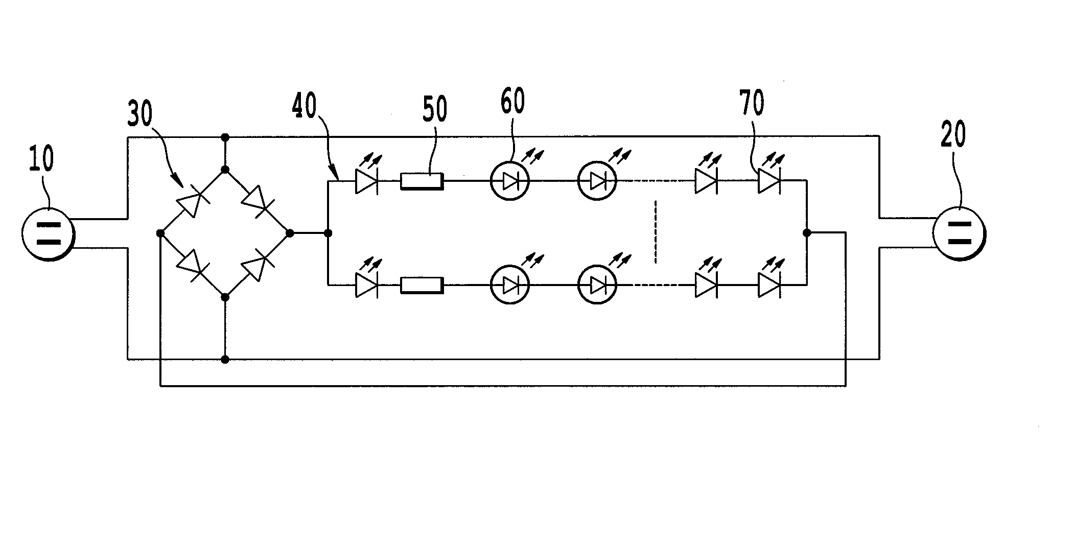
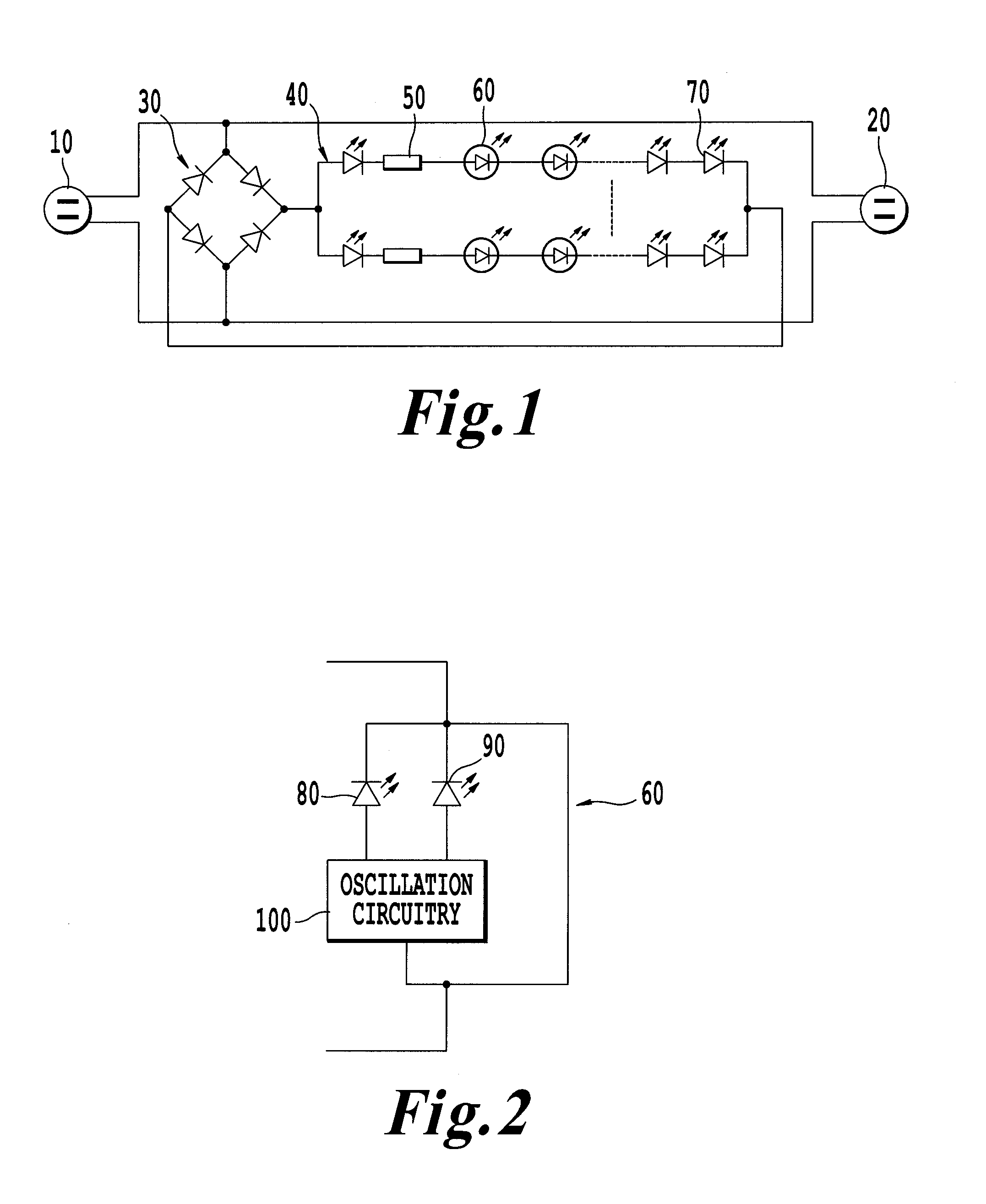
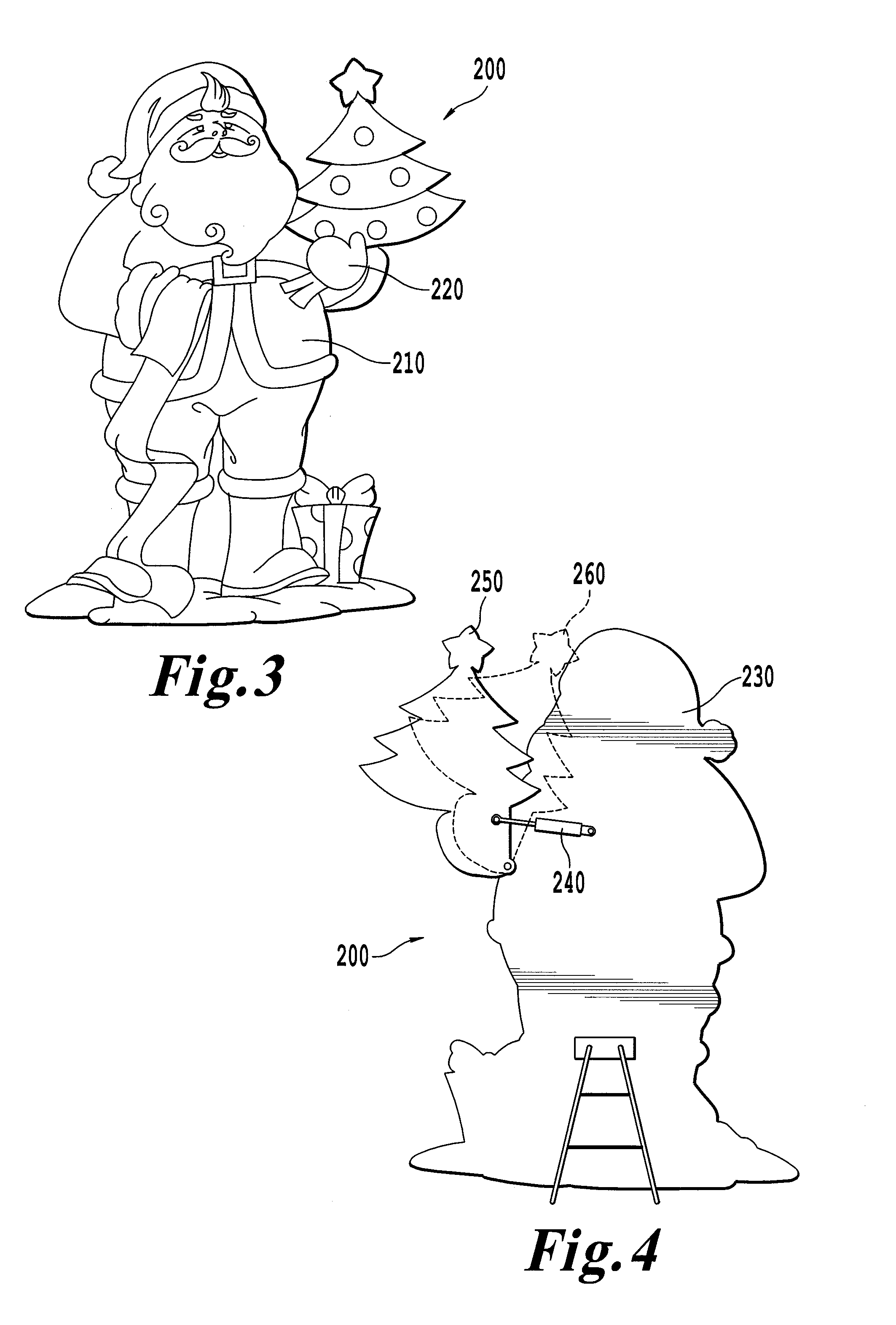
[0019]The effective result of one embodiment of the present invention is as follows: 1) The light branches of the present invention includes a plurality of series connected LED light bulbs, at least one of the LED light bulbs includes two light emitting diodes, the two light emitting diodes twinkle under control of an oscillating circuitry, which optimizes the ornamental effect. 2) The at least two light emitting diodes are configured in different colors or the same color, so as to present more abundant color and offer various color changes. 3) The twinkling light string can be applied in different ornaments designed for every festival article. 4) The outlet of the twinkling light string is an AC (alternating current) outlet, minimizing load impact from the sublevel twinkling light string upon the first level, thereby creating a safer device.

Problems solved by technology

When the filament is electrified, the filament is heated up by electrical energy, thus causing the filament to glow.
The metal element deforms because of the increased temperature, causing the metal element to separate from the filament, creating a short circuit, which shuts off power to the incandescent bulb.
However, traditional twinkling light strings and associated light ornaments incorporating traditional twinkling light strings twinkle randomly in an orderless frequency, due to the different rates of declining performance characteristics of the various incandescent bulbs.
Consequently, traditional twinkling light strings are not capable of performing more sophisticated ornamental functions.
The power consumption of the following sublevel light strings can cause the first-level light string to overload.
In an instance where the first-level light string burns out, a fire hazard may result.

Method used


Image

  • Blinking light string
  • Blinking light string
  • Blinking light string

Examples


Embodiment Construction

[0014]Referring now to the drawings, wherein like reference numerals designate identical or corresponding parts throughout the several views.

[0015]The present inventions have several features, no single one of which is solely responsible for its desirable attributes. Without limiting the scope of the invention as expressed by the claims which follow, its more prominent features will now be discussed briefly. After considering this discussion, one will understand how the present inventions provide several advantages over traditional twinkling light strings.

[0016]Accordingly, one object of the present invention in accordance with the twinkling light string is to provide a twinkling light string capable of stable twinkling in an uniform frequency and with a better ornamental effect.

[0017]To achieve the above objects and in accordance with the purpose of the embodiments of the invention as embodied and broadly described herein, an embodiment of a twinkling light string comprising an AC ...


PUM


Abstract

A twinkling light string includes an AC plug configured to connect to an AC power supply and an AC plug receiver is configured to extend the twinkling light string by receiving another AC plug. A set of light branches including one light branch or a plurality of light branches connected in parallel, each of the light branches including a plurality of LED light bulbs connected in series, at least one of the LED light bulbs including two light emitting diodes, the two light emitting diodes are configured to twinkle under control of oscillating circuitry. Rectifying circuitry is located between the AC plug and the set of light branches. The rectifying circuitry is configured to convert inputted alternating current to direct current and is configured to power the light branches or a plurality of light branches connected in parallel by the direct current.

Description

CROSS REFERENCE TO RELATED APPLICATIONS[0001]This patent specification is based on Chinese Patent Application No. 200720118426.2 filed on Jan. 31, 2007 in the Chinese Patent Office, the entire contents of which are incorporated by reference herein.BACKGROUND OF THE INVENTION[0002]1. Field of the Invention[0003]The present invention is generally related to a light string used for decorative purposes during holidays and festivals. More particularly, the present invention relates to a twinkling light string.[0004]2. Description of the Related Art[0005]Conventional twinkling light strings utilize a twinkling light source, such as a twinkling incandescent bulb. The twinkling incandescent bulb twinkles based on the principle of fluctuations in the conduction path during normal and high temperature changes between a filament and a metal element in the incandescent bulb. When the filament is electrified, the filament is heated up by electrical energy, thus causing the filament to glow. The ...

Claims


Application Information

Patent Timeline
Patent Type & Authority Applications(United States)
IPC IPC(8): F21S4/00
CPCF21S4/001F21Y2101/02F21V23/0407F21S4/10F21Y2115/10
Inventor PAN, KUO-AN
Owner PAN KUO AN
Learn More