
System and method for determining execution path difference in program

a technology of execution path and system method, applied in the field of software performance analysis and diagnostics, can solve problems such as the redundancy of calling paths in complex applications

Active Publication Date: 2008-07-24
SAS INSTITUTE
View PDF18 Cites 24 Cited by
  • Summary
  • Abstract
  • Description
  • Claims
  • Application Information

AI Technical Summary

Benefits of technology

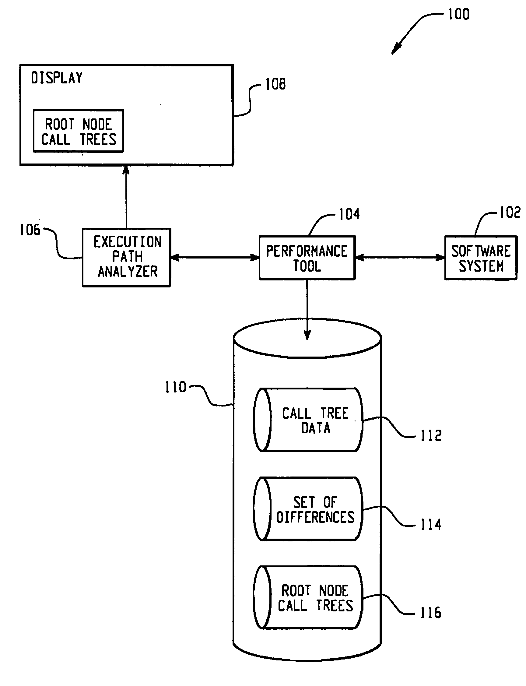
[0009]A system and method for determining execution path differences in a computer-implemented software application is provided herein. A software application under analysis is executed at least twice, thereby generating first and second call tree data and associated first and second sets of execution data describing the at least two executions of the software application. This data is then compared to determine a set of differences between th

Problems solved by technology

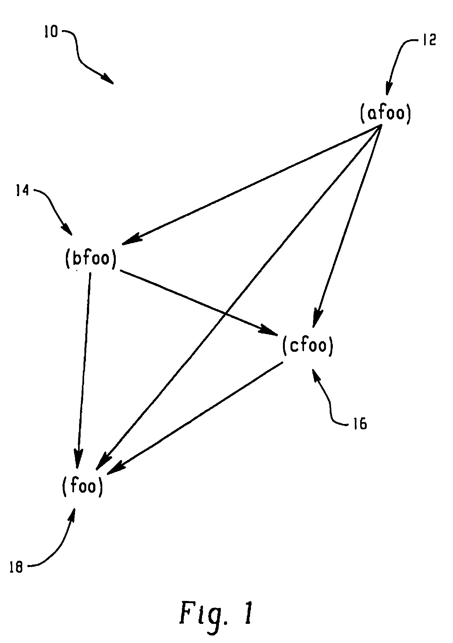
Oftentimes, the calling paths in complex applications can become redundant as between two subroutines, meaning that there are several communication paths between the subroutines.

Method used


Image

  • System and method for determining execution path difference in program
  • System and method for determining execution path difference in program
  • System and method for determining execution path difference in program

Examples


Embodiment Construction

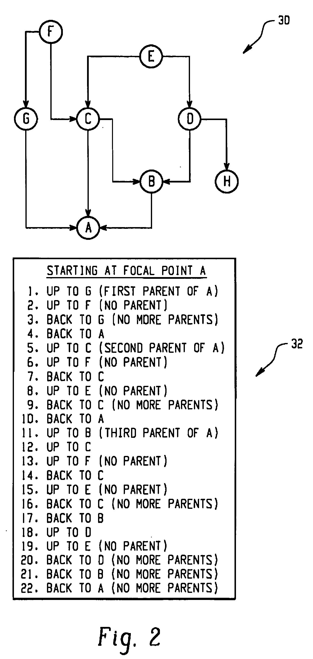
[0019]Turning now to the remaining drawing figures, FIG. 2 is an example node traversal diagram 30 showing a call tree and a method for traversing the nodes of the call tree. In this example, there are eight nodes in the call tree, labeled A through G. The node A is termed the “focal node” in this diagram because it is the node currently under analysis to determine the source of its disparate operation. The “parent tree” of focal node A is shown in FIG. 2, which graphically depicts the full call paths of the nodes calling into the focal node. A “parent node” is a node in the call tree that calls a particular node under consideration, and a “child node” is a node that is called by a particular node under consideration. Other familial relationships apply to the description of the call tree as well. For example, nodes G, C and B are the parent nodes to the focal node A and thus the focal node A is the child node to nodes G, C and B. Node F is a parent node to nodes G and C, and thus it...


PUM


Abstract

A system and method for determining execution path differences in a computer-implemented software application is provided herein. A software application under analysis is executed at least twice, thereby generating first and second call tree data and associated first and second sets of execution data describing the at least two executions of the software application. This data is then compared to determine a set of differences between the first and second executions of the program, the set of differences comprising one or more nodes that are either called differently in the first and second execution paths or executed differently in the first and second sets of execution data. For each node identified in the set of differences, the first and second call trees are then analyzed to identify at least one parent node that is the root cause of the difference in the execution data.

Description

BACKGROUND[0001]1. Technical Field[0002]The technology described in this patent application is generally directed to the field of software performance analysis and diagnostics. More specifically, the technology provides a system and method for determining execution path differences between a plurality of subroutines in a computer program and for determining the root cause of the execution path differences.[0003]2. Description of the Related Art[0004]Complex software applications typically comprise hundreds or even thousands of subroutines or functions, each of the subroutines typically performing a particular function or set of functions. The subroutines of the software application communicate with one another by calling one another in a variety of distinct calling paths. A call path is a communication path between two or more subroutines. Oftentimes, the calling paths in complex applications can become redundant as between two subroutines, meaning that there are several communicati...

Claims


Application Information

Patent Timeline
IPC IPC(8): G06F9/44
CPCG06F11/3612G06F11/3664G06F2201/865G06F11/3466G06F11/32
Inventor CATES, CLAIRE S.
Owner SAS INSTITUTE
Learn More