
Vane Pump With Substantially Constant Regulated Output

a vane pump and substantially constant technology, applied in the direction of machines/engines, liquid fuel engines, positive displacement liquid engines, etc., can solve the problems of reducing fuel efficiency, damage to the engine and/or other components of the engine system, etc., to reduce the length of the moment arm, reduce the amount of control spring, and reduce the effect of constant output pressur

Active Publication Date: 2008-07-24
HANON SYST EFP CANADA LTD
View PDF15 Cites 17 Cited by
  • Summary
  • Abstract
  • Description
  • Claims
  • Application Information

AI Technical Summary

Benefits of technology

[0013]Preferably, the orientation of the control spring also reduces the amount by which the control spring is compressed when the control ring moves from the first position to the second position.
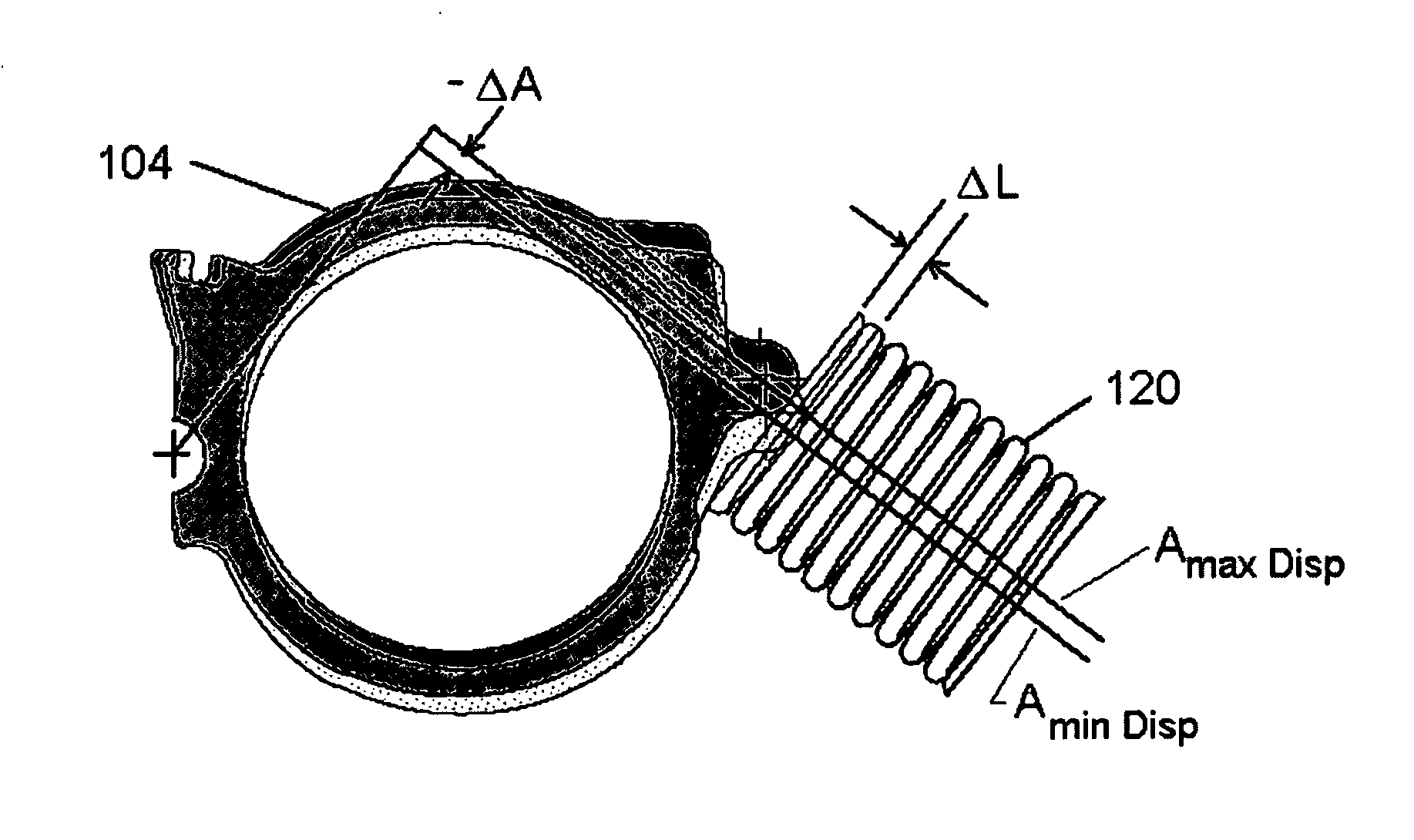
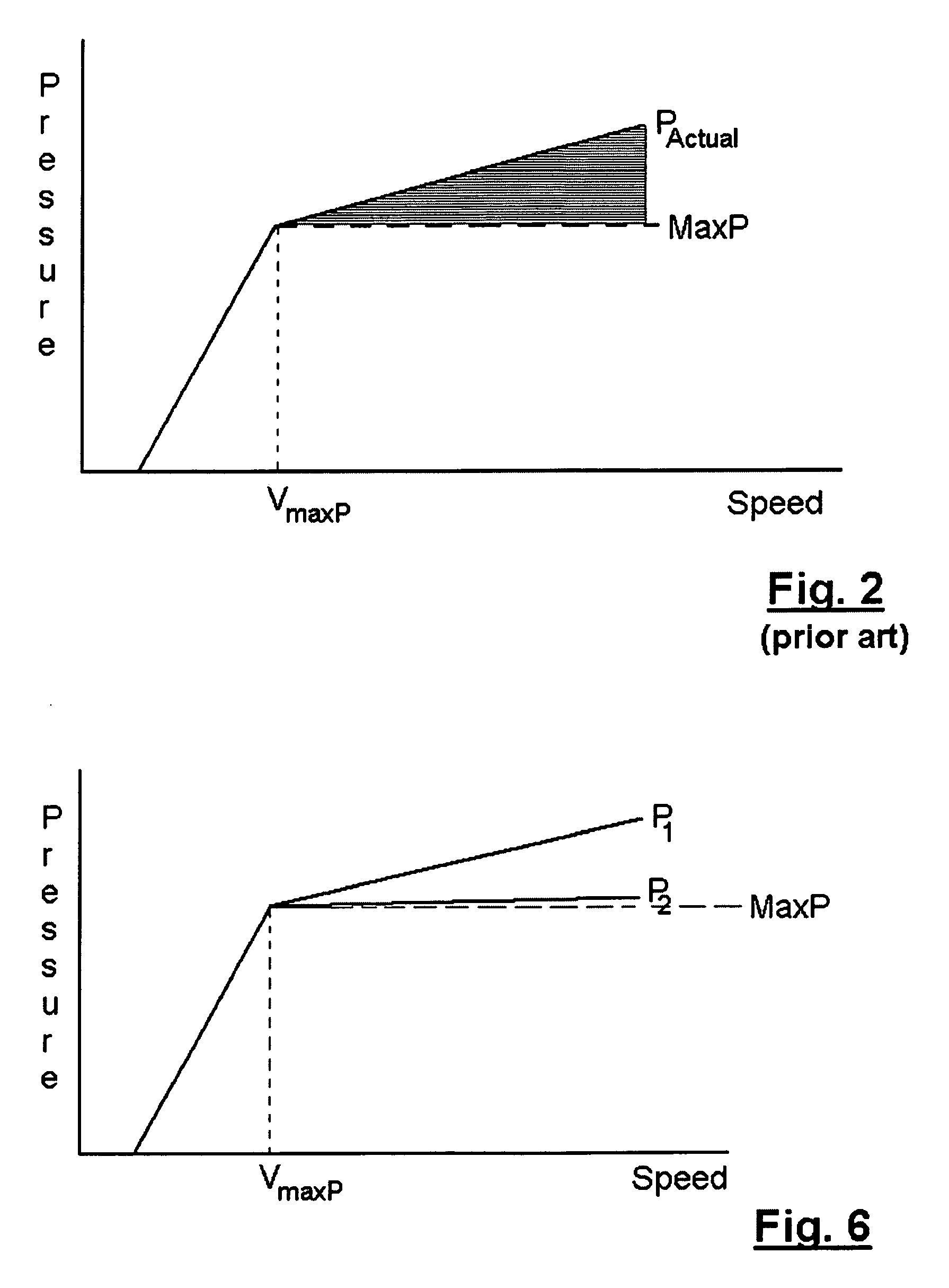
[0014]The present invention provides a variable displacement vane pump which is able to achieve a substantially constant output pressure in its regulated operation region. The longitudinal axis of the control spring of the pump is inclined, with respect to a plane through the rotational axis of the pivot and the contact point between the control ring and the control spring, and this inclination results in a reduction in the length of the moment arm between the spring and the pivot when the control ring of the pump is moved from the maximum displacement position to the minimum displacement position. By reducing the length of this moment arm, the increase in the moment produced by compression of the control spring is offset, resulting in a substantially constant output pressure in the regulated operating range of the pump. The inclination further results in a reduction in the amount by which the control spring is compressed when the control ring moves from the first position to the second position. This reduction in the change in length of the control spring results in a corresponding reduction in the amount by which the spring force exerted by the control spring increases as the control ring moves from the first position to the second position.

Problems solved by technology

The oversupply of lubricating oil is undesired as it wastes energy, reducing fuel efficiency of the engine, and in some applications as the oversupply results in an overpressure which can damage the engine and / or other components of the engine system.

Method used


Image

  • Vane Pump With Substantially Constant Regulated Output
  • Vane Pump With Substantially Constant Regulated Output
  • Vane Pump With Substantially Constant Regulated Output

Examples


Embodiment Construction

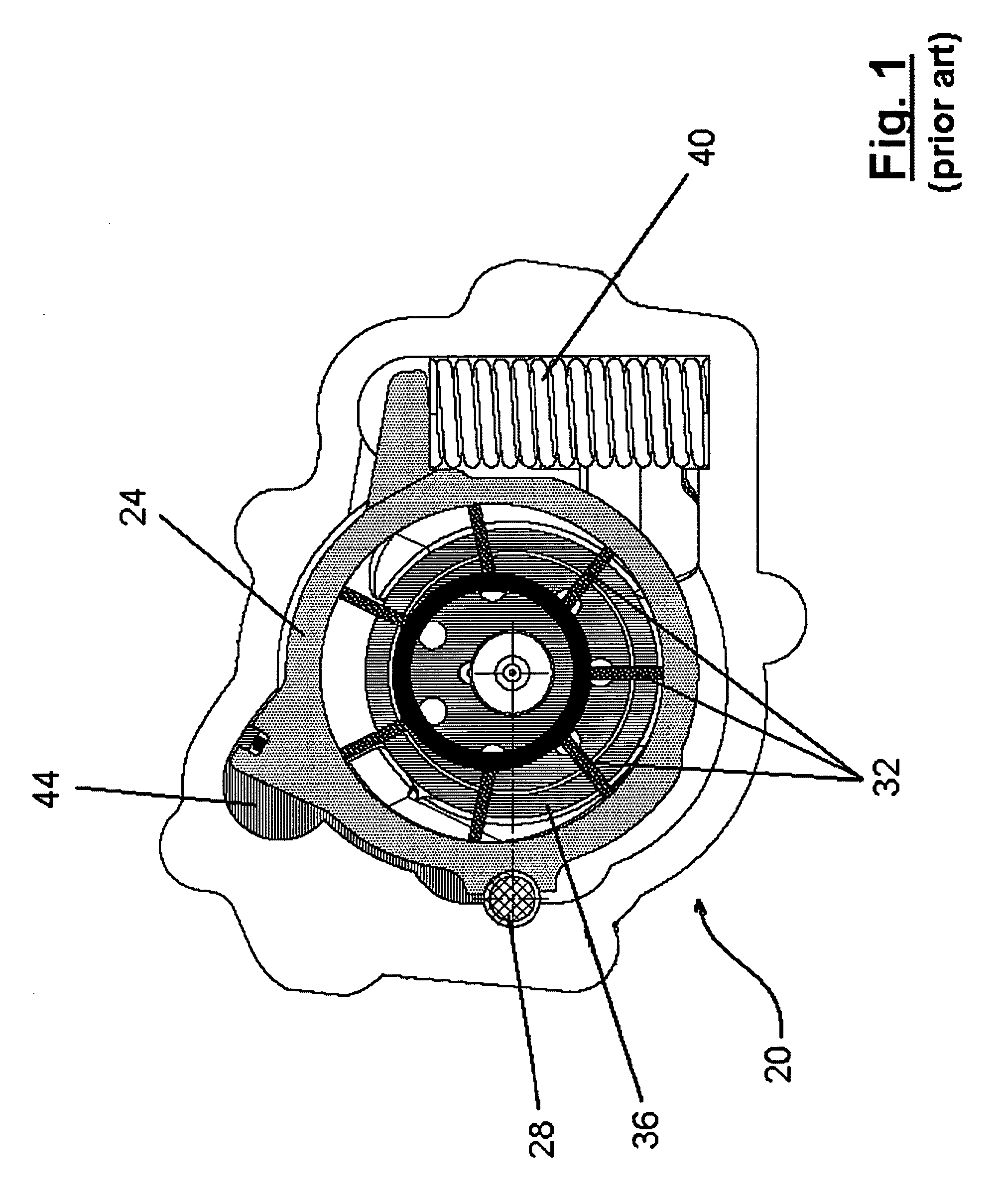
[0022]A prior art variable displacement vane pump is indicated generally at 20 in FIG. 1. Pump 20 includes a control ring 24, which pivots about a pivot pin 28 to alter the degree of eccentricity of the vanes 32 about the rotor 36 of pump 20 to change the displacement of pump 20.

[0023]Control ring 24 is biased to the maximum displacement position (as shown in FIG. 1) by a control spring 40 and a feedback mechanism, in the form of a control chamber 44, generates a force to counter the biasing force of control spring 40 as the pressure of the output of pump 20 increases. Specifically, in this example, control chamber 44 is supplied with pressurized fluid from the output port of pump 20 and that pressurized fluid creates a force on the portion of control ring 24 within chamber 44 and that force biases control ring 24, against control spring 40 towards the minimum displacement position for control ring 24. As will be understood by those of skill in the art, control chamber 44 can be sup...


PUM


Abstract

A variable displacement vane pump is provided which is able to achieve a substantially constant output pressure in its regulated operation region. The longitudinal axis of the control spring of the pump is inclined, with respect to a plane through the rotational axis of the pivot and the contact point between the control ring and the control spring, and this inclination results in a reduction in the length of the moment arm between the spring and the pivot when the control ring of the pump is moved from the maximum displacement position to the minimum displacement position. By reducing the length of this moment arm, the increase in the moment produced by compression of the control spring is offset, resulting in a substantially constant output pressure in the regulated operating range of the pump. The inclination further results in a reduction in the amount by which the control spring is compressed when the control ring moves from the first position to the second position. This reduction in the change in length of the control spring results in a corresponding reduction in the amount by which the spring force exerted by the control spring increases as the control ring moves from the first position to the second position.

Description

FIELD OF THE INVENTION[0001]The present invention relates to a variable displacement vane pump. More specifically, the present invention relates to a variable displacement vane pump which provides a substantially constant output in the regulated portion of its output characteristic.BACKGROUND OF THE INVENTION[0002]Variable displacement vane pumps are well known and are used in a variety of systems. One use for such pumps which is becoming increasingly common is as lubrication oil pumps on internal combustion engines. Lubrication oil pumps in internal combustion engines operate over a wide range of speeds, as the engine operating speed changes, resulting in the output volume and the output pressure (as the output of these pumps is generally supplied to a lubrication system which can be approximately modeled as a fixed size orifice) of the pumps changing with their operating speed.[0003]Generally, an internal combustion engine requires the lubrication oil pressure to increase with eng...

Claims


Application Information

Patent Timeline
IPC IPC(8): F04B49/00
CPCF04C14/226F04C2/3442
Inventor SHULVER, DAVID R.TANASUCA, CEZARWILLIAMSON, MATTHEW
Owner HANON SYST EFP CANADA LTD
Learn More