
Dipole antenna and electronic apparatus using the same

a technology of electronic equipment and dipole antenna, which is applied in the direction of antenna details, antenna feed intermediates, antennas, etc., can solve the problems of inconvenient carrying, high cost, and ineffective optimization of the overall dimension of the television box and the signal receiving quality of the antenna, so as to reduce the manufacturing cost and the dimension of the apparatus, the effect of simple structur

Inactive Publication Date: 2008-07-24
LITE ON TECH CORP
View PDF9 Cites 0 Cited by
  • Summary
  • Abstract
  • Description
  • Claims
  • Application Information

AI Technical Summary

Benefits of technology

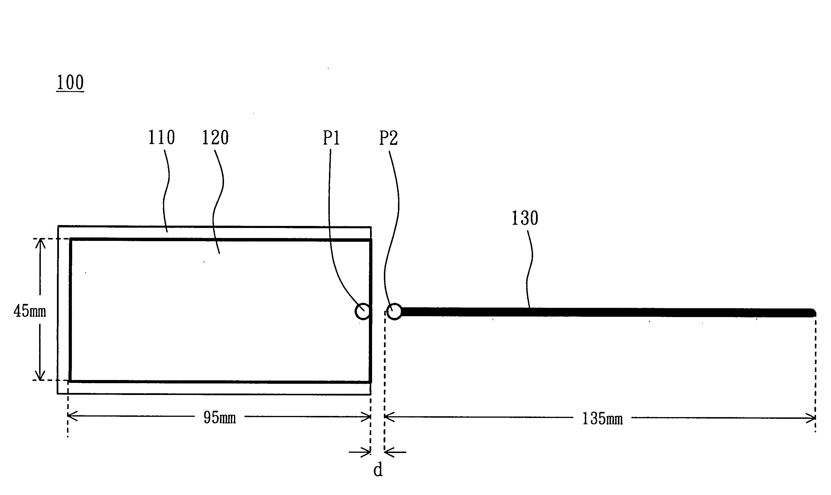
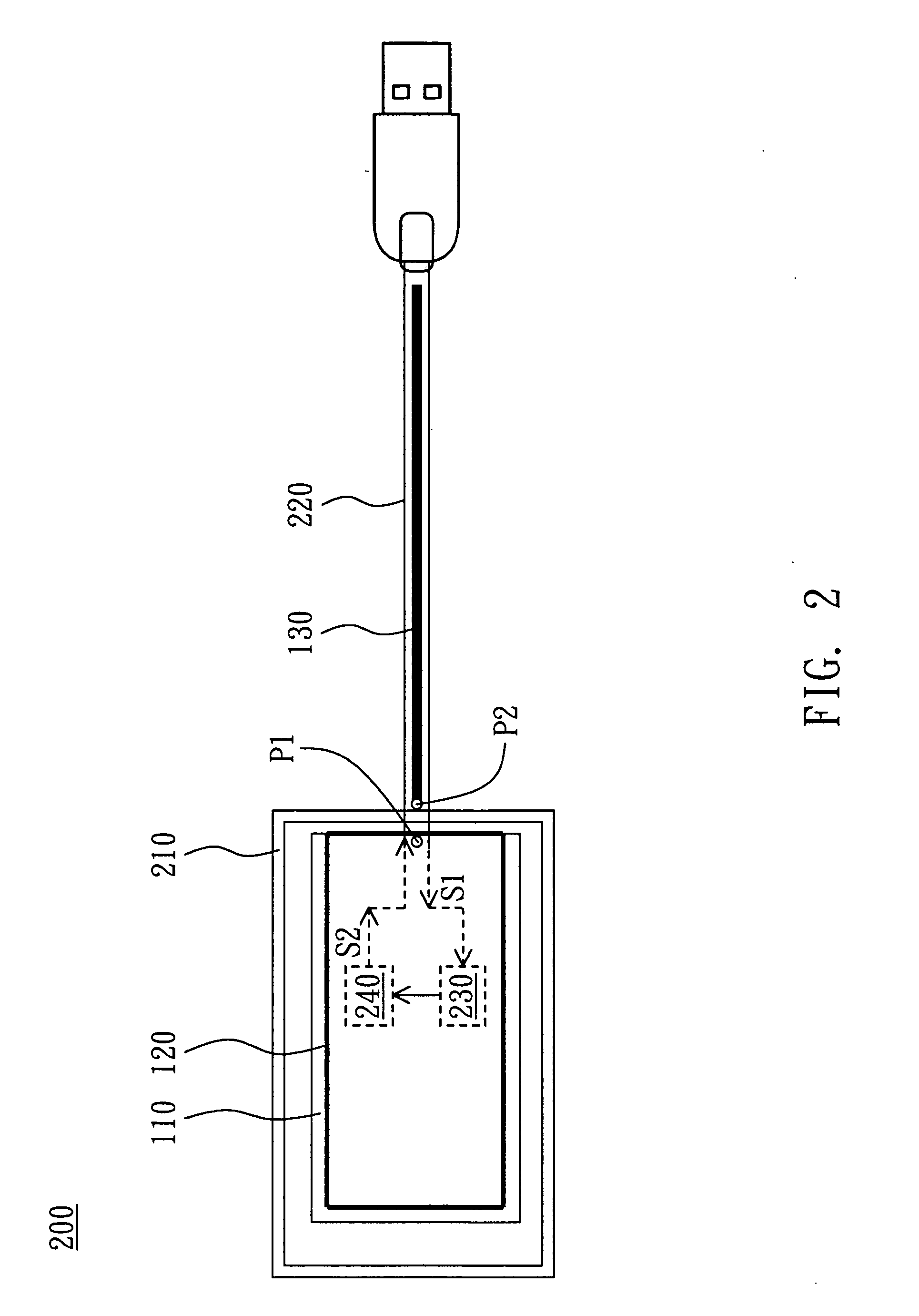
[0007]The invention is directed to a dipole antenna and an electronic apparatus using the same. The dipole antenna and a system circuit of the electronic apparatus (e.g., a digital television receiving apparatus or various plug-and-play apparatuses) may be effectively integrated together according to different dimensions of two metal arms of the antenna so that the manufacturing cost and the dimension of the apparatus may be reduced. Thus, the antenna has a simple structure and can easily be manufactured. In addition, by definition of 2.5:1 VSWR (Voltage Standing Wave Ratio), the impedance bandwidth can also cover the digital television channels (530 to 602 MHz) in Taiwan and thus satisfies the requirement in the industry.

Problems solved by technology

However, the digital television receiving apparatus (i.e., the television box that is frequently seen) is coupled to an external monopole or dipole antenna through an additional coaxial cable, which has a length ranging from about 100 to 150 cm, cannot be carried conveniently, and has the high cost.
However, the overall dimension of the television box and the signal receiving quality of the antenna cannot be effectively optimized.

Method used


Image

  • Dipole antenna and electronic apparatus using the same
  • Dipole antenna and electronic apparatus using the same
  • Dipole antenna and electronic apparatus using the same

Examples


Embodiment Construction

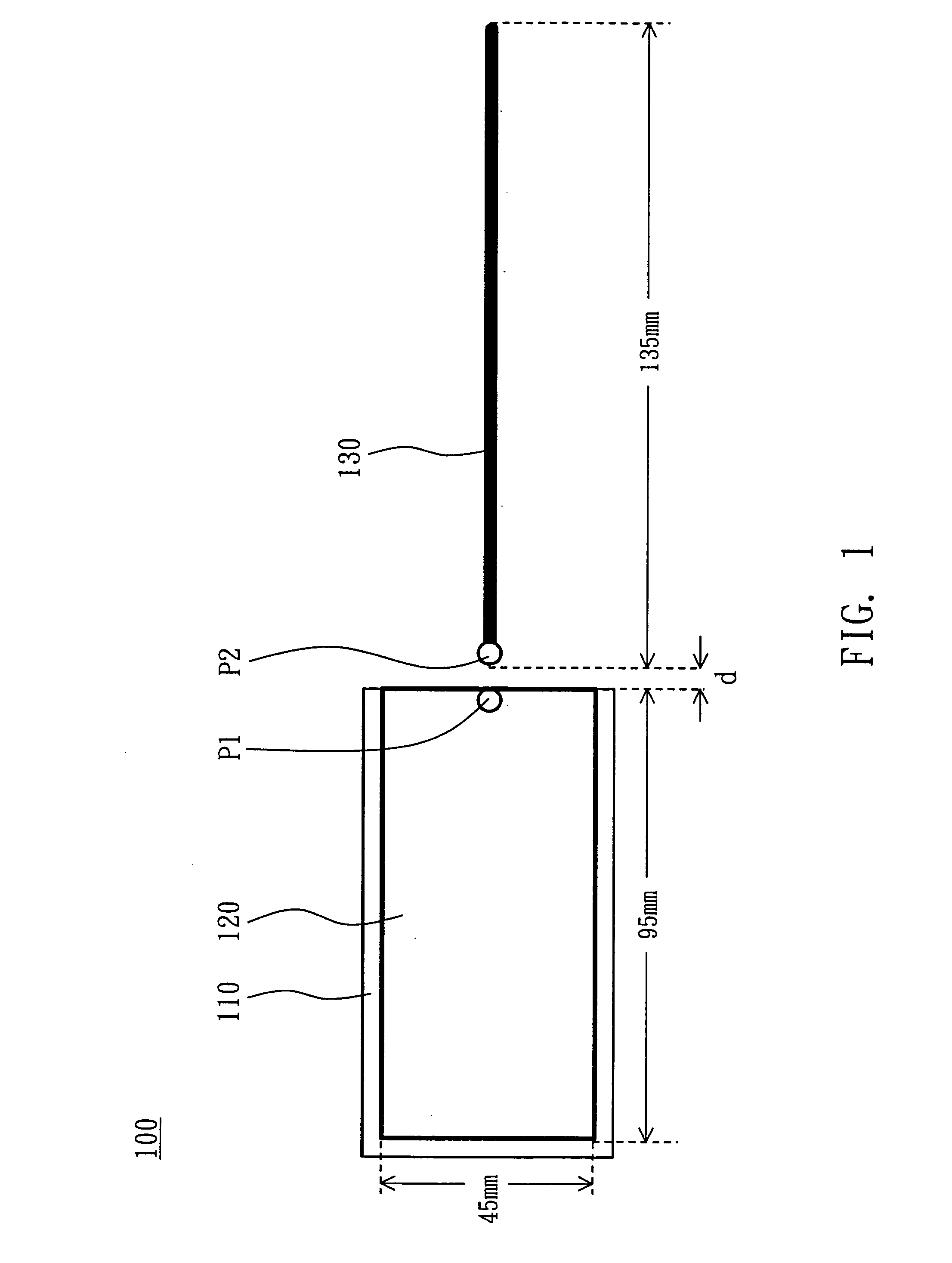
[0017]FIG. 1 is a schematic illustration showing a dipole antenna 100 according to a preferred embodiment of the invention. Referring to FIG. 1, the dipole antenna 100 includes a substrate 110, a radiating metal plate 120 and a radiating metal line 130. For example, the substrate 110 is a multi-layer printed circuit board (PCB), and the radiating metal plate 120 is formed on the substrate 110 by way of etching or printing and has a first signal feeding point P1, which is near a lateral side of the substrate 110. The shape of the radiating metal plate 120 may be changed according to the actual application. For example, the radiating metal plate 120 may have a polygonal shape or an elliptic shape. In this embodiment, the radiating metal plate 120 has a rectangular shape, and a width and a length of the radiating metal plate 120 are respectively 45 mm and 95 mm, as shown in FIG. 1.

[0018]The radiating metal line 130 has a second signal feeding point P2. The gap d between the signal feed...


PUM


Abstract

A dipole antenna includes a substrate, a radiating metal plate and a radiating metal line. The radiating metal plate is disposed on the substrate and has a first signal feeding point near a lateral side of the substrate. The radiating metal line has a second signal feeding point near the first signal feeding point.

Description

[0001]This application claims the benefit of Taiwan application Serial No. 96101964, filed Jan. 18, 2007, the subject matter of which is incorporated herein by reference.BACKGROUND OF THE INVENTION[0002]1. Field of the Invention[0003]The invention in general relates to an antenna, and more particularly to a dipole antenna and an electronic apparatus using the same.[0004]2. Description of the Related Art[0005]With the passed legislation for restricting the import of the build-in digital-television tuner in various main countries in the world and the mandate to stop using analog television, the digital television tends to replace the analog television in the development of the current television industry. Different telecommunication systems and different digital television standards are used in different countries. Three standards, including the DVB-T (Digital Video Broadcasting-Terrestrial) specification in Europe, the ATSC (Advanced Television Systems Committee) specification in the...

Claims


Application Information

Patent Timeline
Patent Type & Authority Applications(United States)
IPC IPC(8): H01Q9/16H01Q1/24
CPCH01Q9/30H01Q1/242
Inventor SU, SAOU-WENTANG, TER-MINGTAI, HORNG-MING
Owner LITE ON TECH CORP
Learn More