
Encapsulating permanent wire connector

Inactive Publication Date: 2008-07-24
FLEXTHERM
View PDF2 Cites 1 Cited by
  • Summary
  • Abstract
  • Description
  • Claims
  • Application Information

AI Technical Summary

Benefits of technology

[0006]Another feature of the present invention is to provide an encapsulating permanent wire connector which is easy and quick to assemble, which provides a permanent wire connection which is electrically insulated and water-proof and which is easy to install.

Problems solved by technology

A disadvantage with these is that one cannot warranty-that the placement of wires is fully secure.
Because these sleeves are flexible the welded connections and the entire assembly remain flexible which makes it more fragile and thus could lead to breakage or damage to the welded connection.
The securement of these sleeves is also a time-consuming and inaccurate process.
Air can also be trapped in these double wall construction shrink sleeves and this could eventually result in corrosion of the welded interconnection.
Further, often these insulating shrink sleeves do not form a perfect seal about the wires and this exposes the leads which are welded and permitting humidity infiltration into the soldered connection resulting in rust formation and affecting the conductivity of the wire or resulting in a wire breakage and short circuit.
This often necessitates breaking ceramic floors which have been disposed over the cement and this is a time-consuming and expensive operation.
Another disadvantage of the interconnection between such wires is that the welded connection and isolating sleeve is of irregular shape.
These connections are also not resistant to impact and because these wires are usually installed by construction workers they are subject to all sorts of abuse caused by people walking over the connectors or subjecting the connectors to excessive shock.
A still further disadvantage of these prior art interconnections is that they are time-consuming to make and, therefore, expensive.

Method used


Image

  • Encapsulating permanent wire connector
  • Encapsulating permanent wire connector
  • Encapsulating permanent wire connector

Examples


Embodiment Construction

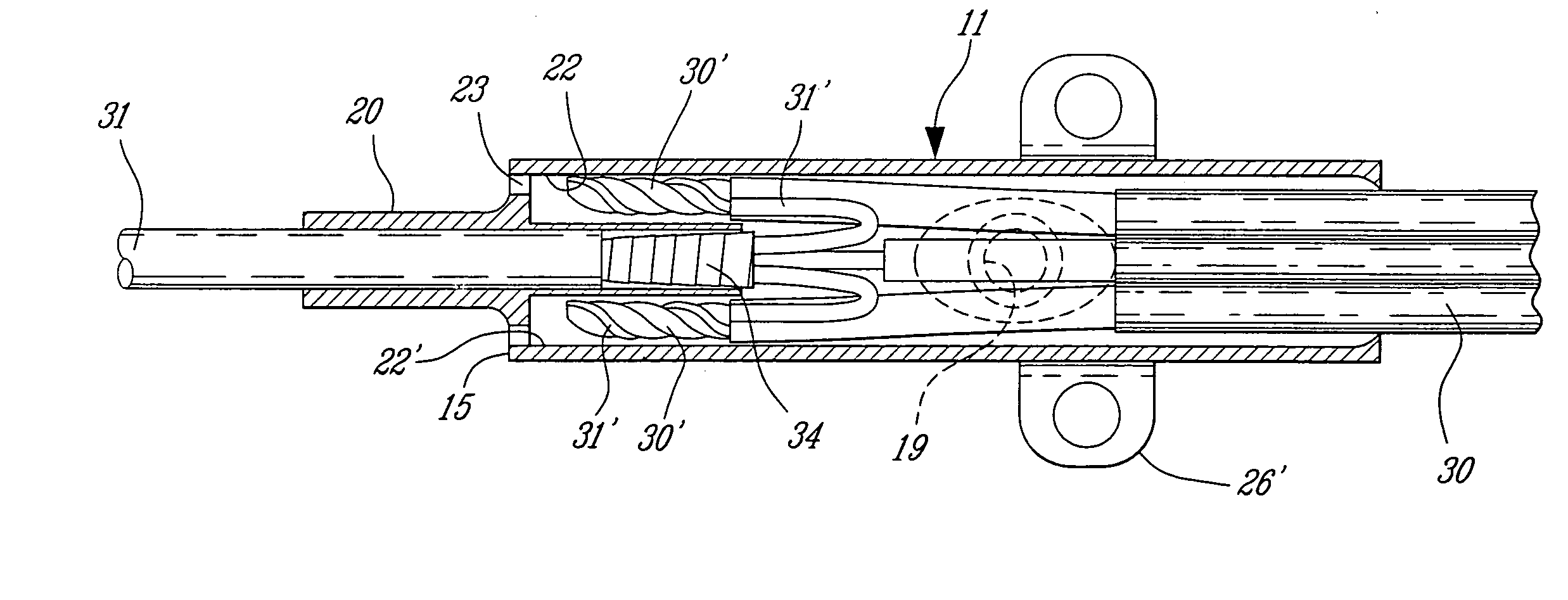
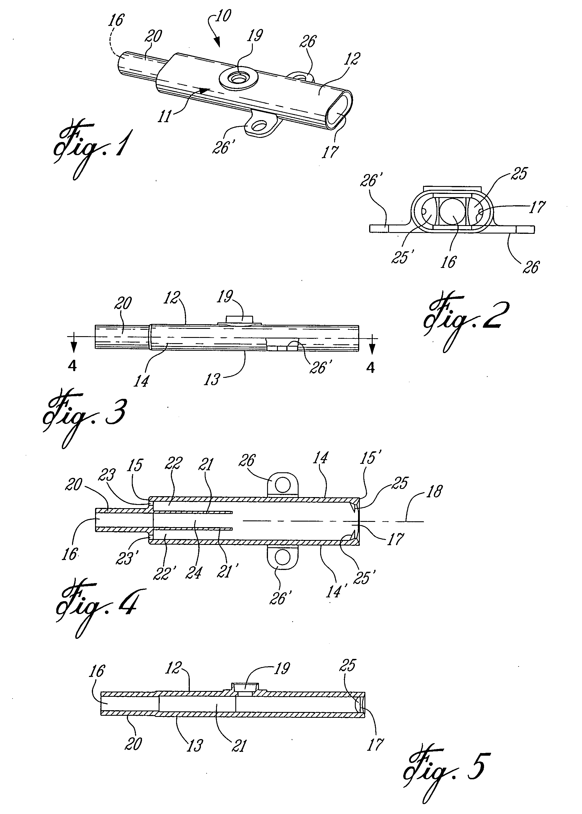
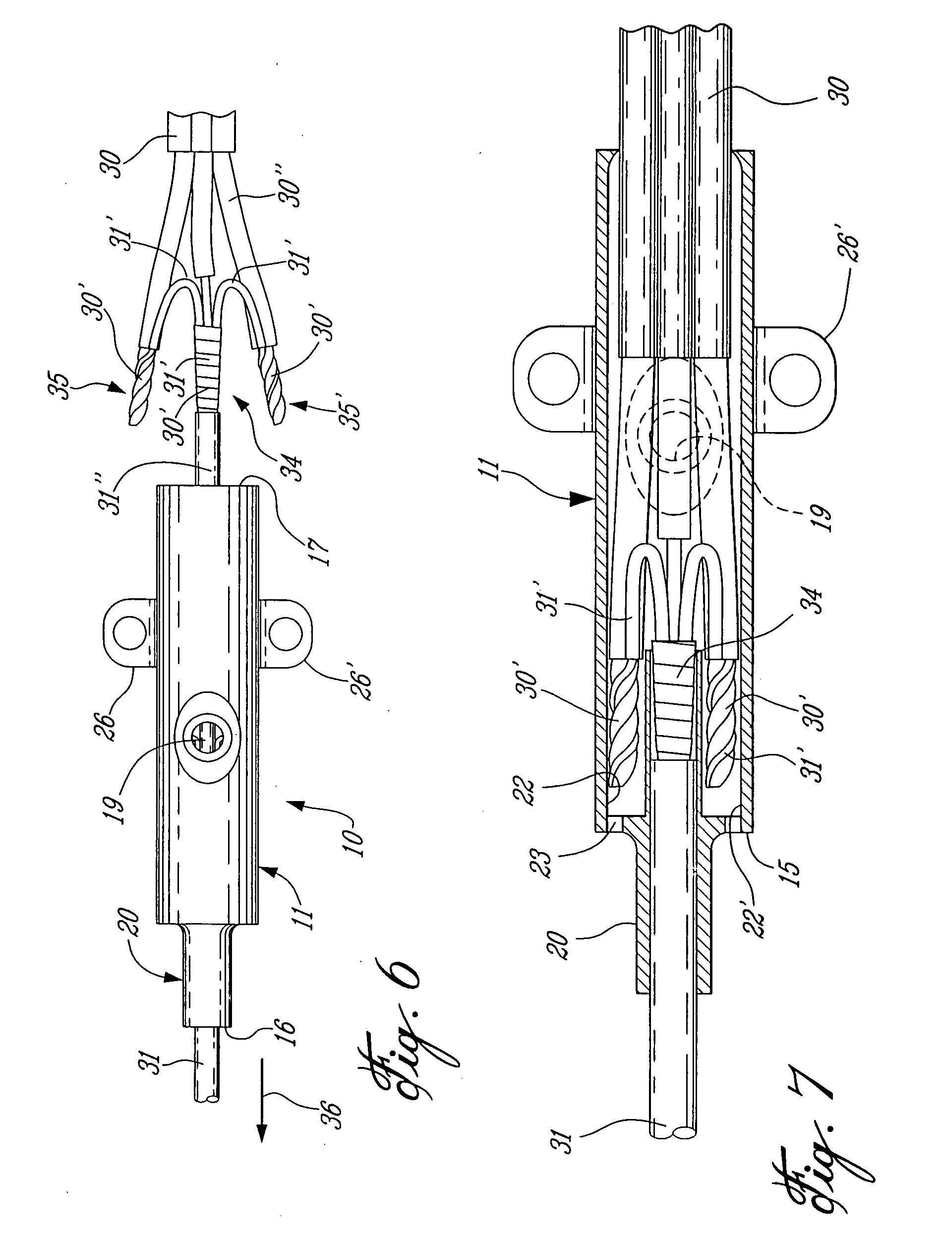
[0020]Referring now to the drawings and more particularly to FIGS. 1 to 5, there will be described the construction of the encapsulating permanent wire connector 10 of the present invention. The connector 10 is comprised of a housing 11 which is molded from a plastics material such as polypropylene or other suitable plastic which is capable of resisting to shocks or acid solutions as found in concrete slurries where such connectors and heating wires are usually embedded. The polypropylene also provides excellent electrical insulation for the connections of the leads of the wires. In the particular application of this connector, wherein it is to be used for interconnecting a cold wire from a thermostat to an electrically heating wire to be embedded in cement it is important that the physical properties of the connector be able to resist to its environmental use and accordingly it needs to also provide water-proof protection to the connections.

[0021]As hereinshown, the housing 11 is a...


PUM


Abstract

An encapsulating permanent wire connector is comprised of a housing provided with a first port and a second port. At least one division wall extends coaxially in a portion of the housing to a side of a straight central axis of the housing and defines an electrically isolating cavity in the housing. The housing has an opening to inject a sealing substance therein. Air evacuation holes are associated with the electrically isolating cavity for the escape of air therefrom when a sealing substance is injected within the housing with soldered wire connections being disposed in the housing and isolated from one another by the electrically isolating cavity. In a preferred embodiment, there are two spaced-apart electrically isolating cavities with a central cavity therebetween.

Description

TECHNICAL FIELD[0001]The present invention relates to an encapsulating permanent wire connector, and particularly, but not exclusively for protecting soldered wire ends of a cold wire to a heating wire and wherein the connector and heating wire are intended to be disposed in a humid mass.BACKGROUND ART[0002]It is customary when fabricating electrically heated floors to connect the wire leads of the heating wires together by solder and then to position a shrinkable isolating sleeve over the soldered interconnection whereby to protect the connection and provide electrical insulation. Shrink sleeves are usually provided with an inside layer of hot glue and they are of a length of about 4 to 5 inches. A disadvantage with these is that one cannot warranty-that the placement of wires is fully secure. These isolating sleeves are required for every welded connection. Because these sleeves are flexible the welded connections and the entire assembly remain flexible which makes it more fragile...

Claims


Application Information

Patent Timeline
IPC IPC(8): H01B17/58
CPCY10S439/936H02G15/16
Inventor MORAND, MICHEL
Owner FLEXTHERM
Learn More