
Semiconductor Wafer Cleaning System

a cleaning system and semiconductor technology, applied in the direction of cleaning process and equipment, cleaning using liquids, cleaning apparatus and processes, etc., can solve the problems of reducing the productivity of wafers, requiring longer cleaning time, and reducing the efficiency of cleaning processes in single stations, so as to improve the cleaning effect, the waiting time of entry into each cleaning station is minimized, and the wafer productivity is significantly improved

Inactive Publication Date: 2008-07-24
K C TECH
View PDF9 Cites 22 Cited by
  • Summary
  • Abstract
  • Description
  • Claims
  • Application Information

AI Technical Summary

Benefits of technology

The present invention provides a semiconductor wafer cleaning system that improves wafer productivity by minimizing the waiting time of entry of wafers into each cleaning station, and separating the supplying structure of chemicals from that of deionized water to improve the cleaning effect. The system also includes a grip structure for wafers in a dry station for rotating and drying, which ensures stable wafer handling even at high speeds. The invention solves the prior art problems of delayed processing and low productivity in semiconductor wafer cleaning.

Problems solved by technology

Accordingly, because both cleaning and rinsing processes are performed in one cleaning system in a prior art semiconductor wafer cleaning system, it is time consuming in performing such processes in a single station.
In addition, such cleaning and rinsing processes must be repeated several times in subsequent stations which accelerates the time consumption greatly and leads to a delay in time so that a wafer polished on a platen of a polishing module needs to wait for entering into the cleaning system and thus causes a lag in view of a whole process and thus lowers wafer productivity due to an impossibility of maintaining the flow of the whole process smoothly.
Therefore, a longer cleaning time is required in order to perform a normal cleaning process which causes productivity to be lowered.
Further, a highly contaminated wafer due to polishing process is inserted directly into a cleaning station through the brushes described above and cleaned immediately, without performing a certain preliminary cleaning process in the prior art cleaning system, so that the contamination of the brushes becomes worse and cleaning power is lowered.
In addition to that, the brushes are shortened in their duration and thus are required to be replaced frequently which leads to inconvenience of maintenance of a CMP tool and an increase of the process costs as well.
When a flat zone type wafer is inserted into a cleaning station in a condition that the flat zone position of the wafer is not aligned exactly, the grip conditions of the respective grip fingers are not uniform and thus the wafer being rotated at a high speed is highly vulnerable to breakdown.
Thus, an alignment of wafer is necessarily required, which lags a whole process due to a time delay by the time to be needed for the alignment and in turn lowers wafer productivity additionally.
Yet, a prior art semiconductor wafer cleaning system has a large structure where respective cleaning, rinsing and drying stations are arranged in a row so that a wide and large space is required to install and apply the prior art cleaning system.

Method used


Image

  • Semiconductor Wafer Cleaning System
  • Semiconductor Wafer Cleaning System
  • Semiconductor Wafer Cleaning System

Examples


Embodiment Construction

[0036]Hereinafter, a semiconductor wafer cleaning system according to preferred embodiments of the present invention is described in more detail by reference to the accompanying drawings.

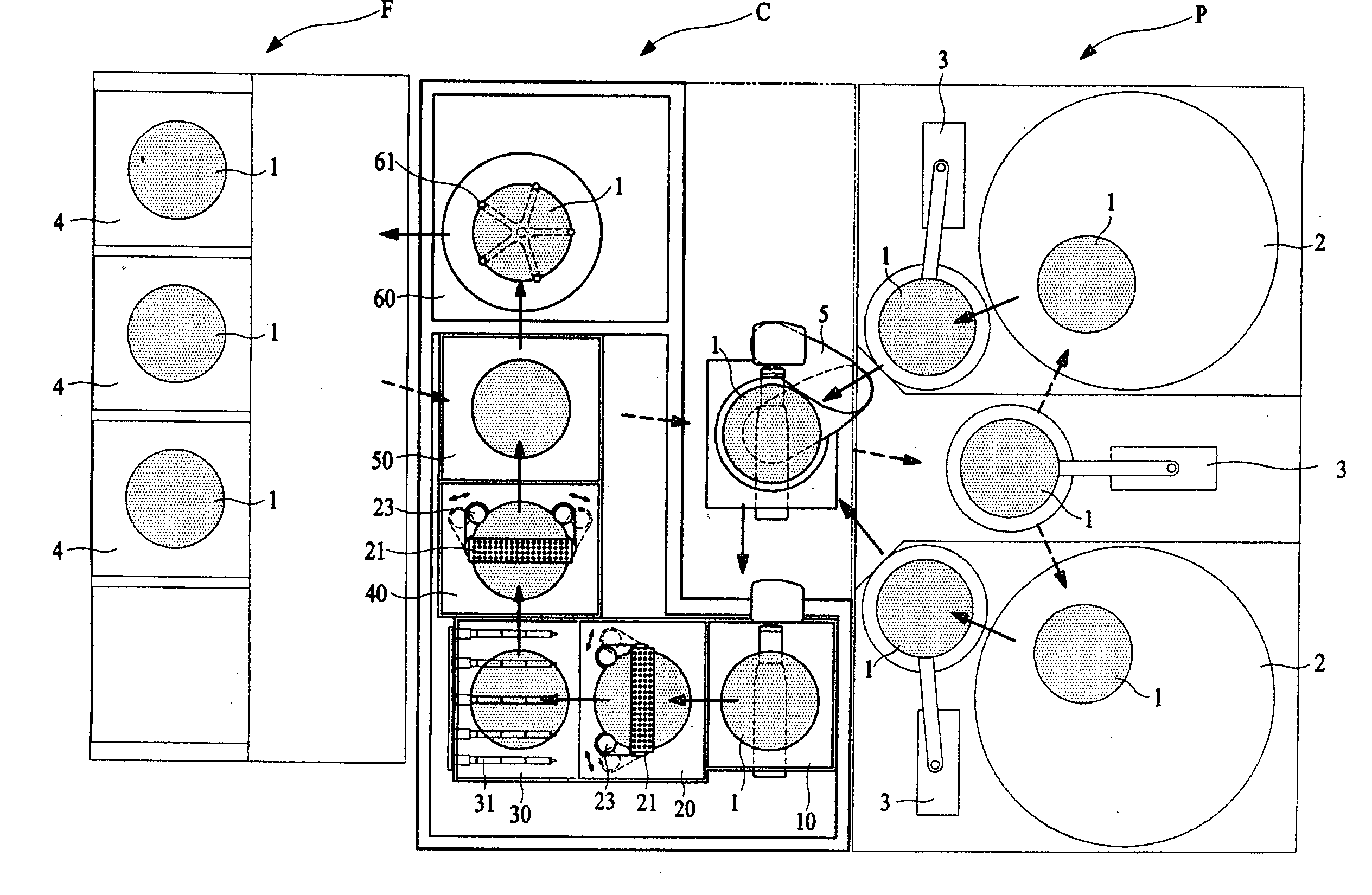
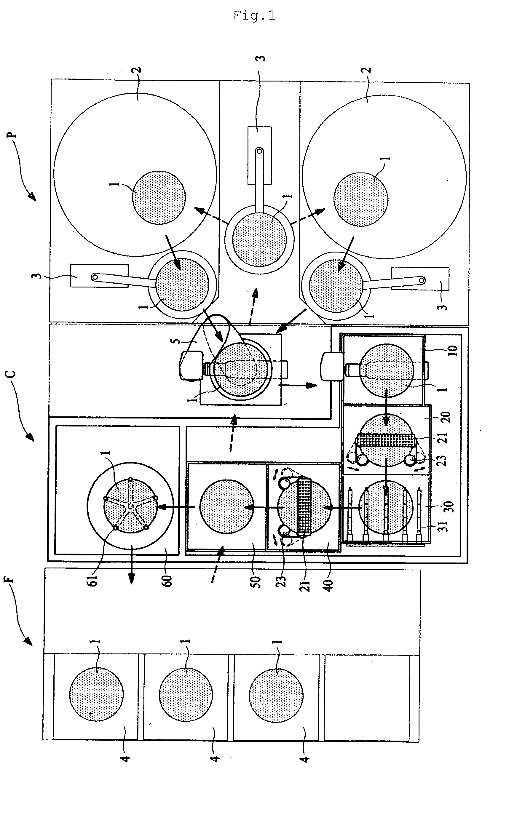
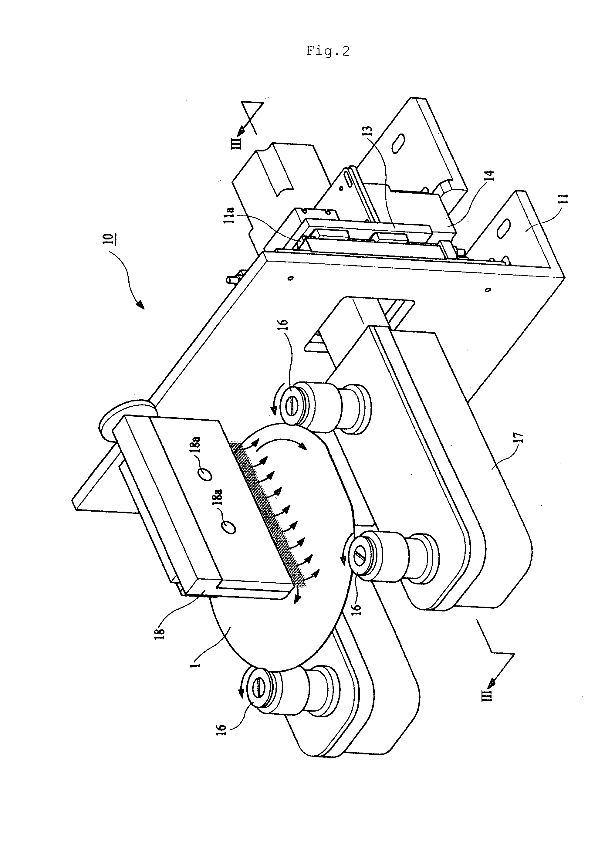
[0037]FIGS. 1 to 11 are drawings for explaining a semiconductor wafer cleaning system C according to the present invention. More specifically, FIG. 1 is a schematic view of a disposition structure regarding respective sections of a semiconductor wafer cleaning system C and a connectivity thereof with peripheral devices such as a polishing module P and a wafer receiving module F in a plane in accordance with the present invention. FIG. 2 is a perspective view of a main structure of a preliminary cleaning station 10 for removing large particles by a water screen type sprayer 18 of deionized water which is applied to a cleaning system C of the present invention. FIG. 3 is a cross-sectional view along the III-III line illustrated in FIG. 2. FIG. 4 is a perspective view of a main structure of a first cle...


PUM


Abstract

The present invention related to a semiconductor wafer cleaning system comprising a preliminary cleaning station for removing particles on a wafer in advance by spraying deionized water thereon; a first cleaning station for cleaning remaining particles firstly by rotating frictionally a pair of brushes disposed to be contacted with a front surface and a back surface of the wafer and by spraying chemicals thereon through a chemical sprayer being provided independently; a first rinsing station for rinsing by spraying a cleaning liquid onto the firstly cleaned wafer at the first cleaning station; a second cleaning station for cleaning particles secondly remained on the front surface and the back surface of the wafer by spraying the chemicals onto the firstly rinsed cleaned wafer at the first rinsing station through a chemical sprayer being provided independently using the same structure and manner as those of the first cleaning station; a second rinsing station for rinsing by spraying the cleaning liquid onto the secondly cleaned wafer at the second cleaning station; and a dry station for drying the remained cleaning liquid using centrifugal force generated by rotating the rinsed wafer at the second rinsing station at a high speed. According to the present invention, a waiting time of entry into each cleaning station is minimized by processing a cleaning operation and a rinsing operation of a surface-polished wafer in a cleaning station and a rinsing station which are provided separately and independently thereby improves wafer productivity significantly by solving a delayed phenomenon in a whole process of wafer manufacturing.

Description

TECHNICAL FIELD[0001]The present invention relates to a semiconductor wafer cleaning system. More specifically, the present invention relates to a semiconductor wafer cleaning system which minimizing a waiting time of entry of wafers into each cleaning station provided separately by independently processing cleaning and rinsing operations of a wafer having a polished surface in each cleaning station, and thus improves wafer productivity by solving a delayed phenomenon in a whole process of wafer manufacturing.BACKGROUND ART[0002]Generally, a manufacturing process of a semiconductor wafer comprises a step of polishing a surface of a wafer by using a chemical mechanical polisher (a CMP tool), etc. and a step of cleaning a wafer for removing particles produced in the step of polishing a surface of a wafer, etc.[0003]The step of cleaning a wafer is performed in various methods by applying various types of cleaning systems of a semiconductor which are known presently in the art. Typicall...

Claims


Application Information

Patent Timeline
Patent Type & Authority Applications(United States)
IPC IPC(8): B08B13/00
CPCH01L21/67028H01L21/68728H01L21/67051H01L21/67046
Inventor YOON, JIN NOKIM, JIN TAE
Owner K C TECH
Learn More