
Nanostructured antireflective optical coating

a technology of anti-reflective coating and nanostructure, applied in the field of optics, can solve the problems of surface reflection coefficient, real coatings cannot reach perfect performance, destructive interference and cancel each other, etc., and achieve the effect of suppressing the reflective capacity of an optical system, reducing the reflective capacity of a transparent optical medium, and minimizing the reflective capacity

Inactive Publication Date: 2008-07-17
OLAR INT
View PDF5 Cites 20 Cited by
  • Summary
  • Abstract
  • Description
  • Claims
  • Application Information

AI Technical Summary

Benefits of technology

The invention is about creating optical coatings that have very low reflective capacity in the visible range of wavelengths. The coatings use nanoparticles that are arranged in a specific pattern to reduce reflective capacity. The nanoparticles are made of metals or dielectrics and are placed close enough to each other to interact with each other. This interaction results in the reduction of reflective capacity, making the optical system appear more transparent. The coatings can be applied to optical lenses and filters to reduce reflection. They are superior to conventional coatings and can also be used on non-transparent surfaces to reduce reflection.

Problems solved by technology

Practical antireflection coatings, however, rely on an intermediate layer not only for its direct reduction of reflection coefficient, but also on use of the interference effect of a thin layer.
If the intensities of the two beams, R1 and R2, are exactly equal, then since they are exactly out of phase, they will destructively interfere and cancel each other.
Real coatings do not reach perfect performance, though they are capable of reducing a surface's reflection coefficient to less than 0.1%.
Other difficulties include finding suitable materials, since few useful substances have the required refractive index (n≈1.23) that will make both reflected rays exactly equal in intensity.
The reflection from all three interfaces produces destructive interference and antireflection.
Therefore, an essential problem associated with improvement of interferential coatings is broadening of the assortment of transparent substances suitable for application onto substrates in the form of homogeneous films [M. Born, E. Wolf. Principles of Optics, Pergamon Press, 1968, Chapter 1; and Ph.
1) They cannot provide the minimal reflective capacity in a wide range of wavelengths of visible light spectrum, i.e., from 400 nm to 800 nm, and in a wide range of angles of incidence 0 to 90°.
2) The known processes are limited in the choice of substances for application of alternating layers. These substances must be transparent in the visible part of the optical spectrum; films made from these substances must be homogeneous and possess appropriate mechanical properties and high adhesive capacity.
3) Widening of an antireflection spectrum requires an increase in the number of layers, and this leads to accelerated aging of interferential coatings.
4) The known interferential antireflective coatings do not provide minimal reflection in a wide range of wavelengths and incidence angles when such coatings are applied onto surfaces of opaque media.
5) A common disadvantage of conventional interferential coating is that their structure, properties, and design must always be considered with reference to the nature, properties, and characteristics of the substrate onto which the coating is applied.
However, the inventor herein is not aware of any published material teaching that interaction between patterned and closely arranged nanoparticles may be used for reducing reflection in an optical coating.

Method used


Image

  • Nanostructured antireflective optical coating
  • Nanostructured antireflective optical coating
  • Nanostructured antireflective optical coating

Examples


Embodiment Construction

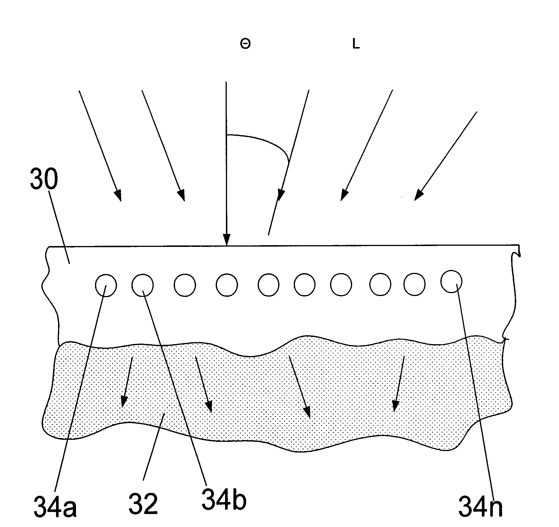
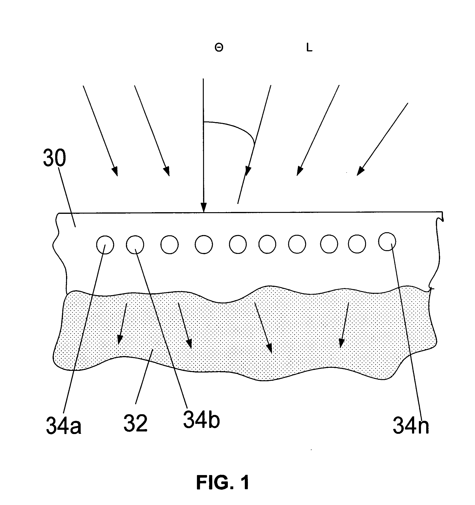
[0048]FIG. 1 is a schematic view of a nanostructured antireflective optical coating 30 of the invention applied onto a body 32 of an arbitrary shape for the purpose of reducing reflective capacity of the aforementioned body 32. Symbol L designates incident light shown by the arrows.

[0049]Reference numerals 34a and 34b through 34n designate a monolayer of nanoparticles embedded in the material of coating 30 and arranged in a predetermined pattern which is described below in more detail. Nanoparticles 34a and 34b through 34n may be substantially identical and form a crystalline pattern of a predetermined symmetry. Nanoparticles can be made from various materials. The tests conducted by the inventor showed that the following materials are suitable for manufacturing nanoparticles that are capable of producing an antireflective effect: metals such as gold, silver, aluminum, copper, etc.; metal alloys of the aforementioned metals; and dielectrics such as glass nanospheres, metal oxides wi...


PUM

PropertyMeasurementUnit
diametersaaaaaaaaaa
angleaaaaaaaaaa
frequencyaaaaaaaaaa

Abstract

An antireflective coating applied onto a substrate in the form of at least one layer of nanoparticles arranged on the aforementioned substrate at equal distances from each other in accordance with a specific nanostructure. The nanoparticles are made from a material that under effect of incident light generates between the neighboring particles optical resonance interaction with a frequency that belongs to a visible optical range. The interaction between the nanoparticles reduces reflection of the incident light. The nanoparticles have a radius in the range of 10 to 100 nm and a pitch between the adjacent particles that ranges between 1.5 diameters to several diameters.

Description

FIELD OF THE INVENTION[0001]The present invention relates to the field of optics, in particular, to antireflective coatings applied onto surfaces of optical components.BACKGROUND OF THE INVENTION[0002]An antireflective coating may be defined as a coating that has a very low coefficient of reflection. The antireflection coating reduces unwanted reflections from surfaces and is commonly used on spectacles and photographic lenses.[0003]Whenever a ray of light moves from one medium to another (e.g., when light enters a sheet of glass after traveling through air), some portion of the light is reflected from the surface (known as the interface) between the two media. The strength of the reflection depends on the refractive indices of the two media as well as the incidence angle. The exact value can be calculated using the Fresnel equations.[0004]When the light meets the interface at normal incidence (i.e. perpendicularly to the surface), the intensity of the separated light is characteriz...

Claims


Application Information

Patent Timeline
Patent Type & Authority Applications(United States)
IPC IPC(8): B32B5/16
CPCY10T428/25G02B1/118
Inventor GADOMSKY, OLEG NIKOLAEVICH
Owner OLAR INT
Learn More