
Disk Centering Assembly And Spindle Hub

a technology of spindle hub and disk centering assembly, which is applied in the direction of data recording, record carrier contruction details, instruments, etc., can solve the problems of built-in errors, negative impact on the performance of the disk drive that contains this disk, and adversely affect the writing of electronic data and information onto the disk surface, etc., to eliminate or minimize the problems associated with the

Inactive Publication Date: 2008-07-17
LASERRES S PTE
View PDF14 Cites 2 Cited by
  • Summary
  • Abstract
  • Description
  • Claims
  • Application Information

AI Technical Summary

Benefits of technology

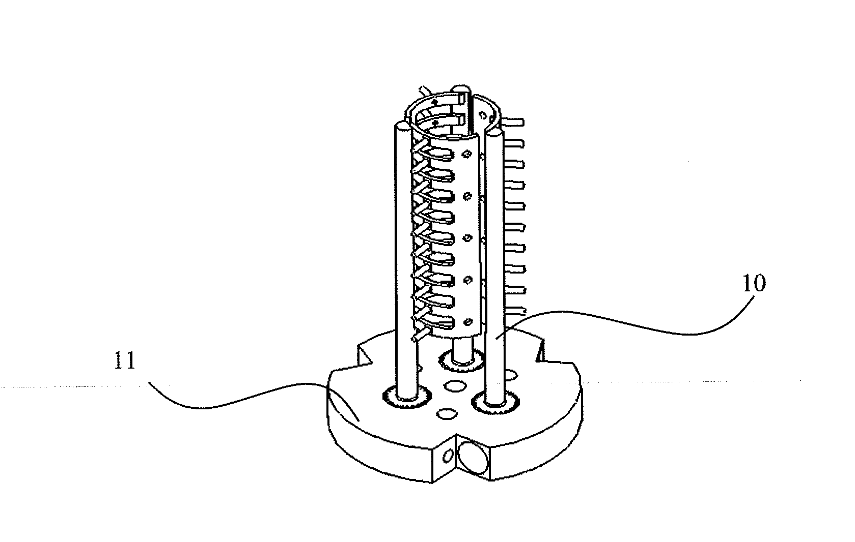
[0006]The present invention intends to eliminate or minimize the problems associated with current available centering techniques by contacting the same surface of the disk when in the spindle that will be used in the disk drive and using centering fingers in the hub that are machined in place to the same length on the spindle while it is rotating. This guarantees that the spindle rotational axis is coincident with the inner diameter of the disk.
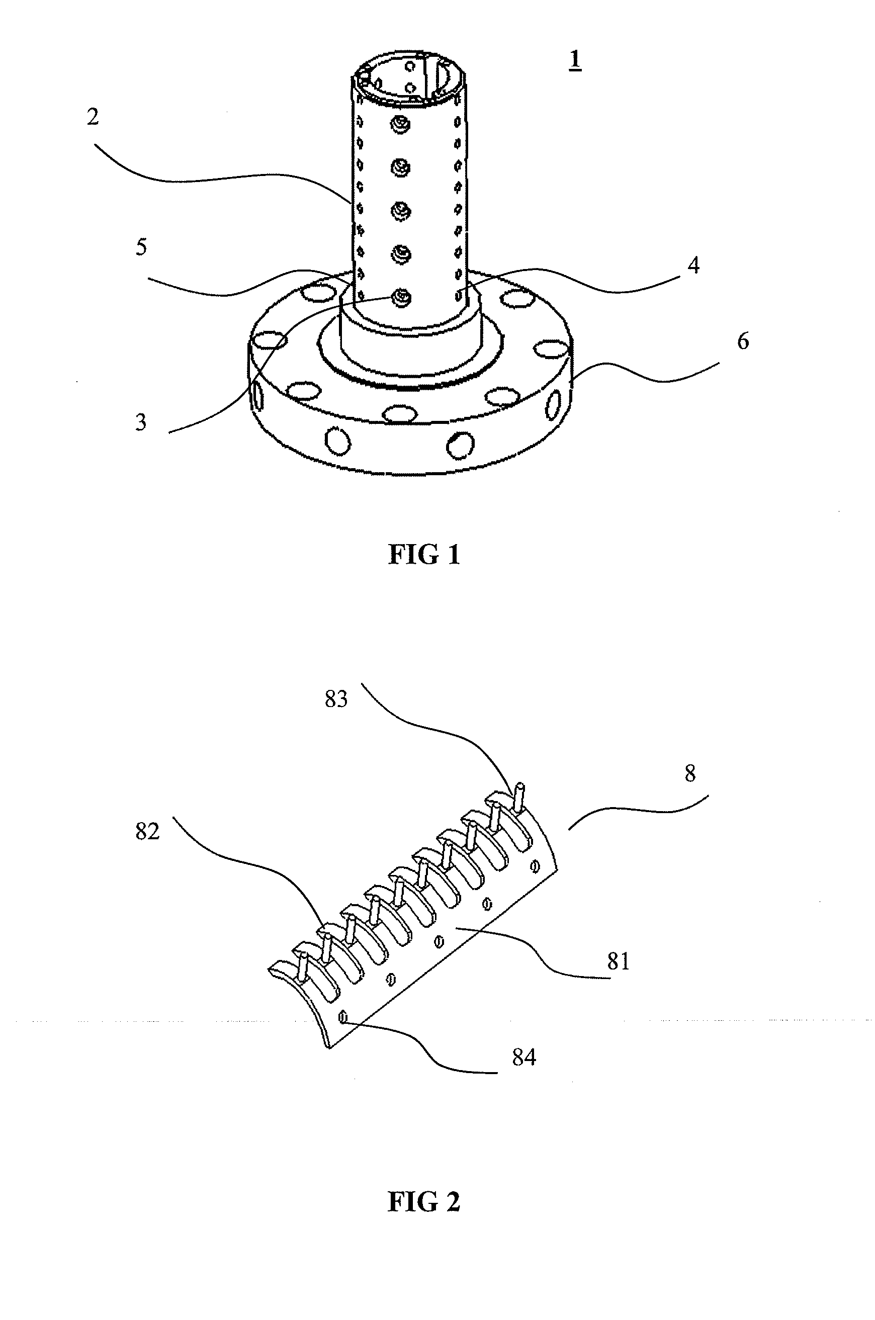
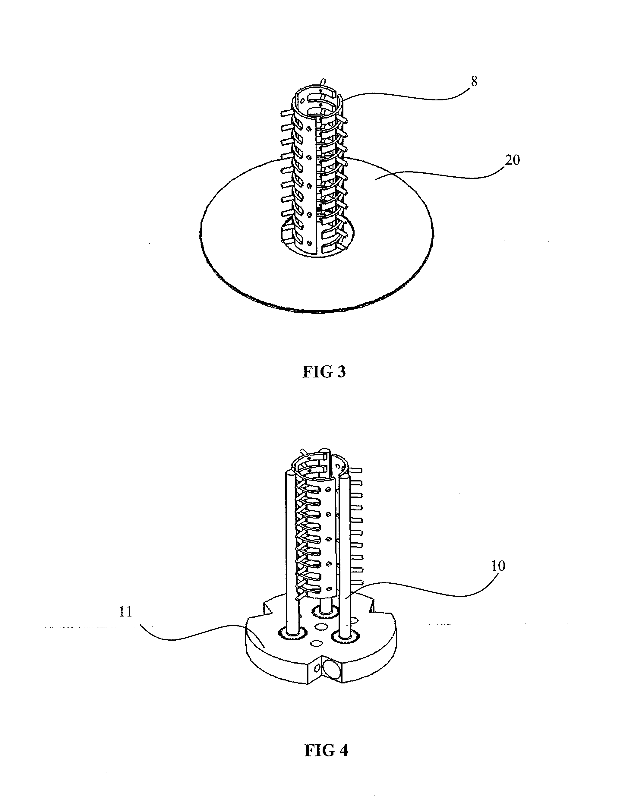
[0007]One embodiment of the present invention provides a centering assembly for centering a plurality of disks being assembled onto a spindle hub. The centering assembly comprises a plurality of curved leaf springs for providing means for centering the plurality of disks by contacting their inner diameters, and a curved leaf springs actuator system for operating the plurality of curved leaf springs; thereby the curved leaf springs actuator system controls the contact between the plurality of curved leaf springs and the inner diameter of the disks, resulting in the centering of the disks being assembled on the spindle hub.

Problems solved by technology

It is evident that when the stacked disks are offset from the center of rotation of a spindle, vibrations will be caused, and the resultant vibrations can adversely affect the writing of electronic data and information onto the disk surface.
If this information is poorly written onto the disk, it will have a negative impact on the performance of the disk drive that contains this disk.
This approach had two inherent problems.
These two problems cause a built-in error that failed the currently available devices to achieve the hoped-for performance gains.

Method used


Image

  • Disk Centering Assembly And Spindle Hub
  • Disk Centering Assembly And Spindle Hub
  • Disk Centering Assembly And Spindle Hub

Examples


Embodiment Construction

[0026]The present invention may be understood more readily by reference to the following detailed description of certain embodiments of the invention.

[0027]Throughout this application, where publications are referenced, the disclosures of these publications are hereby incorporated by reference, in their entireties, into this application in order to more fully describe the state of art to which this invention pertains.

[0028]In the following detailed description, specific details are set forth in order to provide a thorough understanding of the invention. However, it will be understood by those skilled in the relevant art that the present invention may be practiced without these specific details. In other instances, well-known methods, procedures, components, and materials have not been described in detail so as not to obscure the present invention.

[0029]The present invention provides a centering mechanism to ensure that disks are centered around the rotation axis during the assembly ...


PUM

PropertyMeasurementUnit
inner diametersaaaaaaaaaa
inner diameteraaaaaaaaaa
flexibleaaaaaaaaaa

Abstract

The present invention provides a centering assembly for centering a plurality of disks being assembled onto a spindle hub, and further provides a spindle hub being capable of centering disks being assembled.

Description

RELATED APPLICATION[0001]This application claims the benefit under 35 U.S.C. 119(e) of U.S. Provisional Application Ser. No. 60 / 884,608, filed 11 Jan. 2007 with a title of SPINDLE HUB WITH A MULTIDISK CENTERING DEVICE, which is herein incorporated by reference.FIELD OF THE INVENTION[0002]The present invention relates to servowriters, and more particularly to a disk centering assembly for centering multiple disks being assembled on a spindle hub, and further to a spindle hub with a disk centering assembly.BACKGROUND OF THE INVENTION[0003]A typical media servowriter comprises a hub and an air-bearing spindle motor with a rotating shaft, wherein the hub is attached to the spindle air bearing so that the hub can be rotated by the rotating shaft of the air-bearing spindle motor. Usually, the hub has the capacity of receiving a disk-stack with multiple disks and spacers. During servo-track writing, the rotary motion of the air-bearing spindle motor spins the hub and hence the disk-stack i...

Claims


Application Information

Patent Timeline
Patent Type & Authority Applications(United States)
IPC IPC(8): G11B17/08
CPCG11B33/0477
Inventor LAI, KIEN WEEMORARU, ALEXGOH, JUI KIAT
Owner LASERRES S PTE
Learn More