Back plate structure of plasma display panel

a back plate and display panel technology, applied in the direction of electrical discharge tubes, gas-filled discharge tubes, electric discharge tubes, etc., can solve the problems of poor illumination efficiency of image cells, poor quality of phosphor materials, and flickering noise on display panels, so as to eliminate flickering noise, improve illumination efficiency, and improve the effect of efficiency

Inactive Publication Date: 2008-07-17
CHUNGHWA PICTURE TUBES LTD
View PDF5 Cites 4 Cited by
  • Summary
  • Abstract
  • Description
  • Claims
  • Application Information

AI Technical Summary

Benefits of technology

[0009]In order to solve the aforementioned problems of the poor illumination efficiency and flicker-noises on display panel in a conventional PDP, one object of the present invention is to provide a structure with projections on barrier ribs to eliminate flicker-noises on the display panel and increase the illumination efficiency.
[0010]One object of the present invention is to provide a st ructure with projections on barrier ribs for the back plate of a PDP to increase the packing density of the phosphor material, and so as to enlarge the discharge space of the discharge cell.
[0011]One object of the present invention is to provide a structure with projections on barrier ribs for the back plate of a PDP, wherein the horizontal barrier ribs and the vertical barrier ribs have height difference to improve the exhausting efficiency during the printing process of the phosphor paste.
[0012]Consequently, a structure with projections on barrier ribs for the back plate of a PDP in the present invention can improve the nonuniform thickness of the phosphor material in the discharge cell and increase the packing density of the phosphor material to enlarge the exciting area. By this way, it can resolve the problem of the flicker-noises on the display panel, and increase the process yield and illumination efficiency.

Problems solved by technology

Thus, thickness uniformity on the phosphor materials is not in good quality after the solvent of the phosphor paste 26 is evaporated by a firing procedure.
As a result, the illumination efficiency of the image cell is poor and flicker-noises would be produced on the display panel.

Method used


Image

  • Back plate structure of plasma display panel
  • Back plate structure of plasma display panel
  • Back plate structure of plasma display panel

Examples


Embodiment Construction

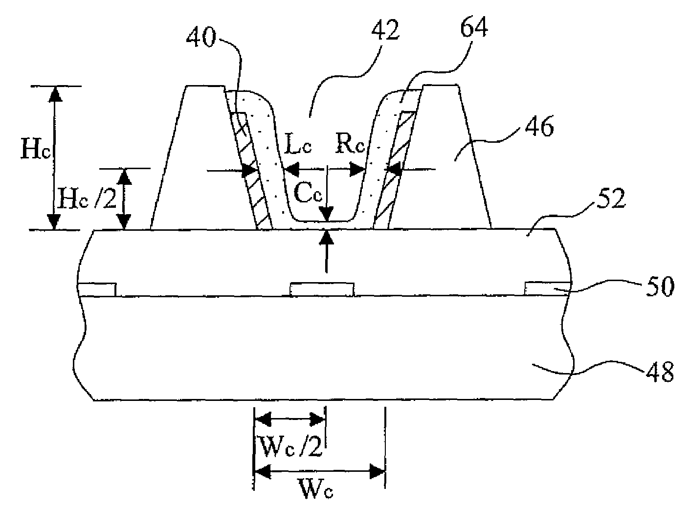
[0038]Regarding to one embodiment of the present invention from FIG.2A to FIG. 2C, FIG.2A is a top-view schematic diagram of partial discharge cells, FIG.2B and FIG.2C are the top-view and cubic schematic diagrams of a single discharge cell respectively. The horizontal barrier ribs 46 and the vertical barrier ribs 44 are crossed over to form a plurality of lattice-like discharge cells 42, wherein the 8 vertical barrier ribs 44 and the horizontal barrier ribs 46 intersect to form right angles for an enclosed space on each discharge cell 42. In this embodiment, each of two adjacent horizontal barrier ribs 46 respectively has a projection 40 protruded to each of the discharge cells 42, wherein the height of the projection 40 can be equal to or smaller than which of the horizontal barrier ribs 46. The height of the projection 40 is smaller than which of the horizontal barrier ribs 46 in this embodiment, as shown in FIG.2C.

[0039]In this embodiment, a phosphor material is printed on the b...


PUM


Abstract

A back plate structure of the plasma display panel is provided. The horizontal barrier ribs and the vertical barrier ribs are crossed over to form the I at t i c e - Ii k e discharge cells. The horizontal barrier ribs or the vertical barr i e r r i b s have t h e projections p rot rude d to t h e discharge cells, which can make the air exhaust from the sides of the projections during the printing of the phosphor paste. The nonuniform-thickness phenomenon caused by the bubbles in the phosphor material printed on the bottom-surface of the discharge cell is improved, and so flicker-noises on the display panel are eliminated. Furthermore, the discharge space is increased owing to the increased packing-density of the phosphor material. Therefore, the illumination efficiency of the PDP is promoted. Besides, the horizontal barrier rib and the vertical barrier rib may also be designed to have a height difference to improve the exhausting efficiency during the printing process of the phosphor paste.

Description

BACKGROUND OF THE INVENTION[0001]1. Field of the Invention[0002]The present invention relates to a structure on barrier rib for the back plate of the Plasma Display Panel (PDP), and more particularly, to a structure with projections on the barrier ribs.[0003]2. Description of the Prior Art[0004]Recently, the technology is developing rapidly on various types of flat panel displays, such as the Liquid Crystal Display (LCD), Field Emission Display (FED) and plasma display panel (PDP). In the different Flat Panel Displays (FPDs), the PDP has many advantages including simple structure, easily to be produced as a large-scale display, longer life time, widely viewing angle which is greater than 160°, thinner module, space saving and not heavy. As the result, it is widely applied on large-scale display apparatuses, such as a large-scale FPD television.[0005]The basic technology theory on PDP is that an electrical field applys to the inert gas, for instance, Ne, He and Xe, to produce a disch...

Claims


Application Information

Patent Timeline
Patent Type & Authority Applications(United States)
IPC IPC(8): H01J17/49
CPCH01J11/12H01J2211/365H01J2211/363H01J11/36
Inventor CHANG, CHAO-JEN
Owner CHUNGHWA PICTURE TUBES LTD
Why Eureka
Try Eureka