Eureka AIR delivers breakthrough ideas for toughest innovation challenges, trusted by R&D personnel around the world.

Methods and systems for monitoring structures and systems

a monitoring system and structure technology, applied in the direction of alarms, structural/machine measurement, instruments, etc., can solve the problems of consuming significant amounts of power, affecting the health of the structure,

Active Publication Date: 2008-07-10
THE BOEING CO
View PDF10 Cites 50 Cited by
  • Summary
  • Abstract
  • Description
  • Claims
  • Application Information

AI Technical Summary

Benefits of technology

The patent describes a system for monitoring the health of structures and components of an object, such as an aircraft. The system includes multiple sensor systems placed on the object that detect data related to its health. The sensor systems communicate wirelessly with a processing system, which uses an ontology and reasoning module to analyze the sensor data and determine its context. This context is then used to fuse the data and create a database of information about the overall object being monitored. The processing system can also include a situation awareness analyzer that uses the data to determine the overall state of the object. The technical effect of this system is to provide a more efficient and effective way to monitor the health of structures and components of an object, allowing for early detection and timely maintenance.

Problems solved by technology

Installation of the wires themselves are cost-prohibitive due to the distances over which the wires must pass, weight prohibitive due to the amount of the wiring, or infeasible in many other situations due to the environment where the sensor itself and respective wiring are located.
However, transmitting the raw data via a large bandwidth wireless system may consume significant amounts of power and create unnecessary network traffic.
However, reducing the data available for analysis also reduces the effectiveness of the analysis.

Method used


Image

  • Methods and systems for monitoring structures and systems
  • Methods and systems for monitoring structures and systems
  • Methods and systems for monitoring structures and systems

Examples


Embodiment Construction

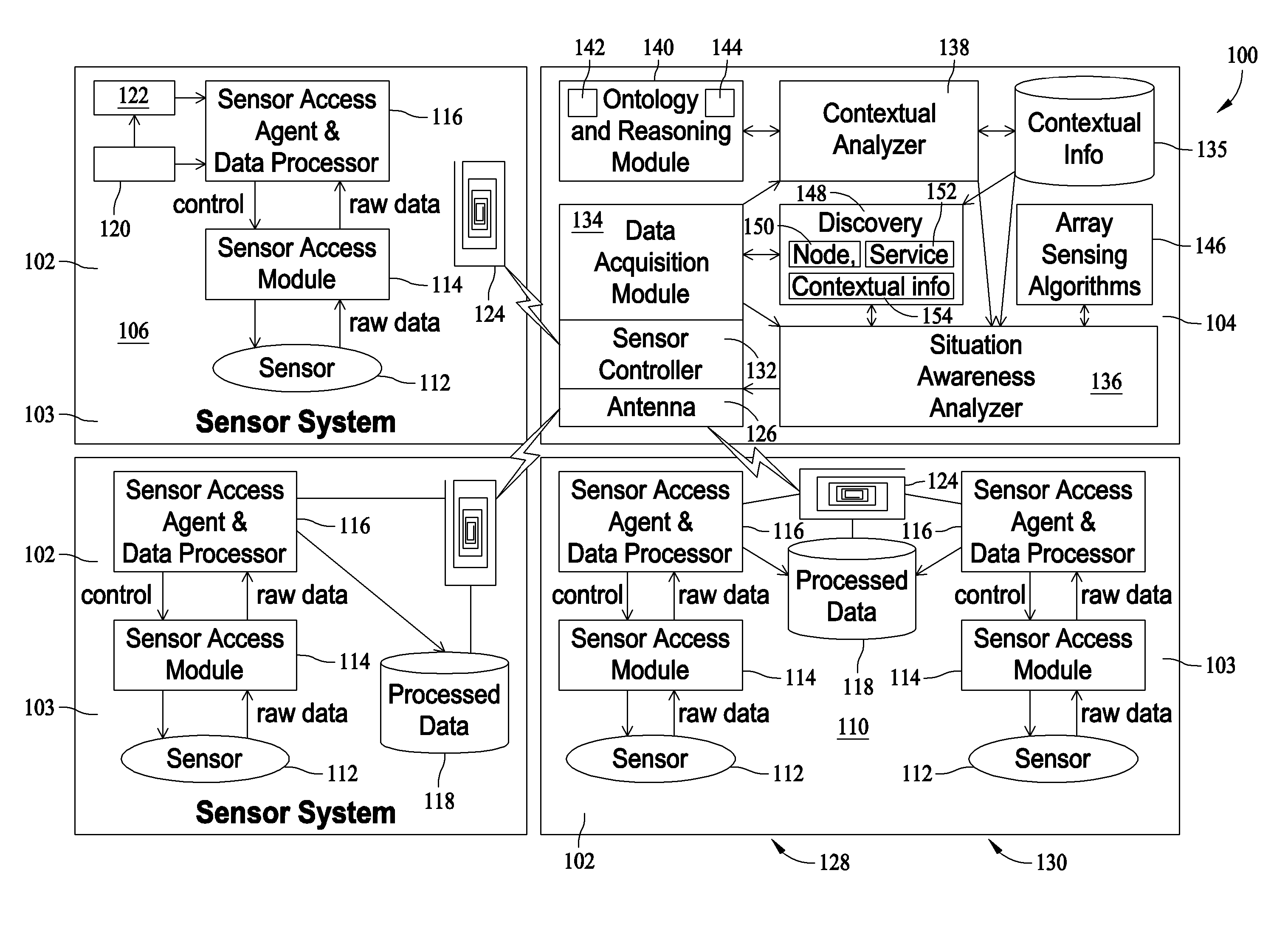
[0012]FIG. 1 is schematic block diagram of a Structure and Systems Health Monitoring System (SSHMS) 100 in accordance with an exemplary embodiment of the present invention. In the exemplary embodiment, SSHMS 100 includes at least one sensor system 102 and at least one onboard processing system 104. Sensor system 102 may include a variety of sensor system types. For example, a single sensor system 106 may include only a single sensor and may not include an onboard storage memory capability. A memory sensor system 108 may include a single sensor and an onboard storage memory for relatively long term storage of data. A multi-sensor system 110 may include a plurality of sensors and may include an onboard storage memory for relatively long term storage of data.

[0013]In the exemplary embodiment, sensor systems 102 generally include a sensor 112, a sensor access module 114, and a sensor access agent and data processor 116. Sensor systems 108 and 110 also include an onboard memory 118 for s...


PUM


Abstract

Methods and systems for structural and component health monitoring are provided. A system includes a plurality of sensor systems positioned about an object to be monitored and a processing system communicatively coupled to at least one of said plurality of sensor systems wherein the processing system includes an ontology and reasoning module configured to model the object to be monitored, reason about the received sensor data associated with the object to be monitored and reason about the relationships between the received sensor data to fuse the data into contextual information for the overall object to be monitored and a contextual analyzer configured to transmit the received sensor data to said ontology and reasoning module and to store the information into a contextual information database.

Description

BACKGROUND OF THE INVENTION[0001]This invention relates generally to structure and system health monitoring and more particularly, to methods and systems for monitoring structure and system health using networked smart wireless sensor devices.[0002]At least some known applications for wireless communication networks include industrial control and monitoring, intelligent agriculture, asset and inventory tracking, and security. Typical wireless sensing systems comprise wireless sensors that passively gather large amounts of data from an environment, which is typically transmitted to a host node for evaluation by an individual specifically trained to manually evaluate the information as time permits. This typical sensor system sometimes includes conversion of the signal from analog to digital and / or signal conditioning. The raw time-series data is typically transmitted in its entirety to a host node where it is sometimes stored indefinitely and analyzed very infrequently.[0003]A conven...

Claims


Application Information

Patent Timeline
Patent Type & Authority Applications(United States)
IPC IPC(8): G01M19/00G01M99/00
CPCG01N29/14G01N29/2475G01N29/2481G07C5/085G01N2291/2694G07C5/008G01N2291/0258
Inventor MATSEN, MARC R.GEORGESON, GARY E.WESTERMAN, EVERETTPORAD, KENNETHAYYAGARI, ARUNUNG, KEVINBATTLES, CRAIG FARRISBLACKWELL, DAVID
Owner THE BOEING CO
Why Eureka
Eureka Blog
Learn More