
Test chamber apparatus

a test chamber and apparatus technology, applied in the direction of electrical testing, measurement devices, instruments, etc., can solve the problems of inability to maintain the desired inside space, inability to properly carry out tests on the hdd, and inability to accurately control the air pressur

Inactive Publication Date: 2008-07-10
HITACHI GLOBAL STORAGE TECH NETHERLANDS BV
View PDF6 Cites 1 Cited by
  • Summary
  • Abstract
  • Description
  • Claims
  • Application Information

AI Technical Summary

Benefits of technology

[0020]According to embodiments of the present invention, in a test chamber apparatus, the sealing property of the depressurized space for setting the test subject device can be maintained so that accurate air pressure control for the depressurized space is achieved.

Problems solved by technology

If the inside space is not properly sealed, the inside space cannot be maintained under a desired air pressure so that the tests on the HDD cannot be carried out properly.
In addition, the inside space cannot be maintained at a desired temperature so that the tests on the HDD cannot be carried out properly.
In the above-described method for passing a cable through a hole provided on the wall of the sealed space, air passing through the inside of the cable may impair the sealing capability of the sealed space.
Besides, since the cable is fixed to the wall with a resin material, if the cable is broken or a different type of test on the HDD is performed, it cannot be replaced easily.
The method to set both of the HDD and the test computer inside the above-described sealed space requires a larger volume of depressurized space so that it is difficult to control air pressure accurately and delicately within the space.

Method used


Image

  • Test chamber apparatus
  • Test chamber apparatus
  • Test chamber apparatus

Examples


Embodiment Construction

[0014]Embodiments of the present invention relate to a test chamber apparatus, and in particular to a test chamber apparatus including a depressurized space for placing a test subject device.

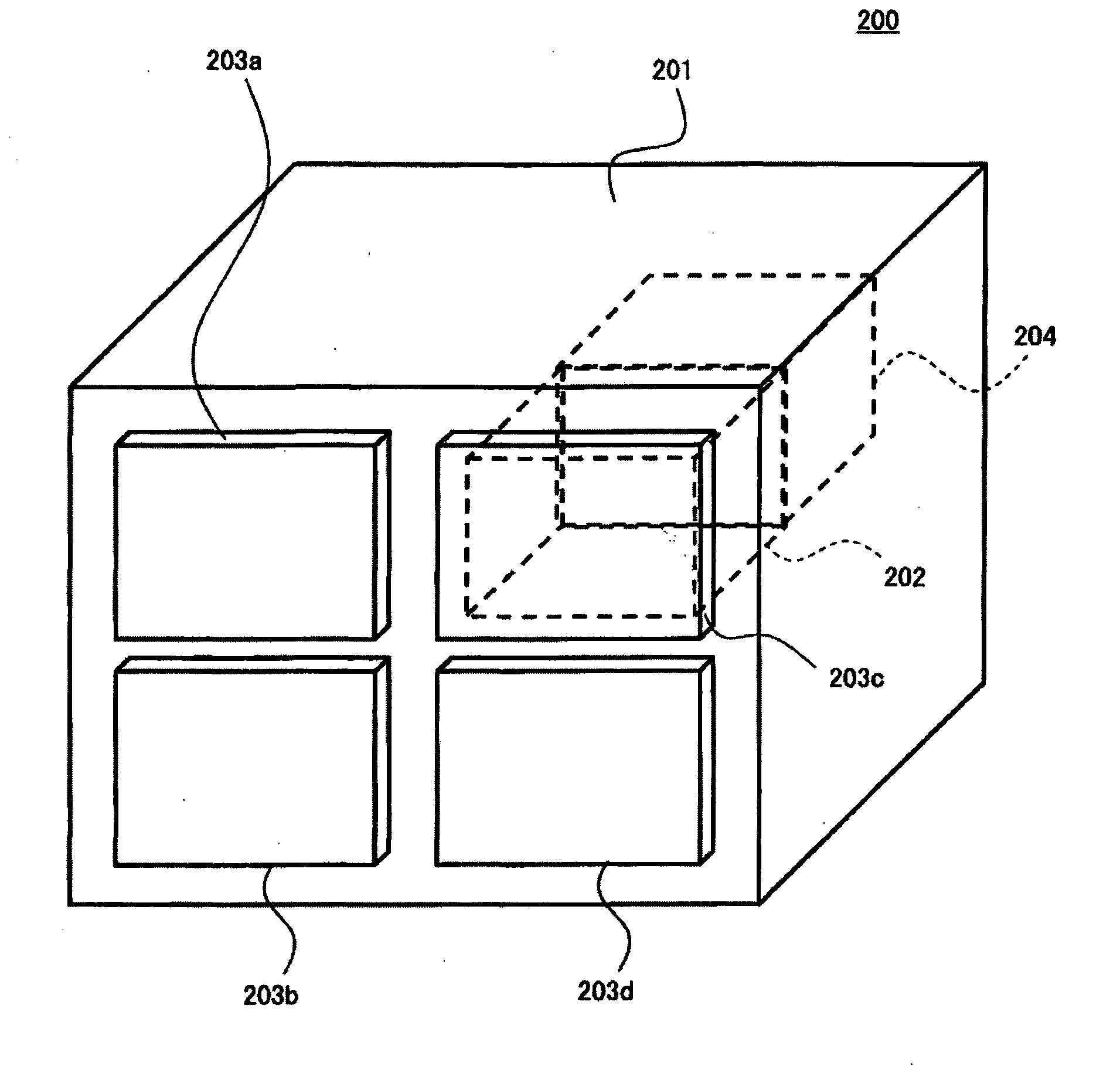
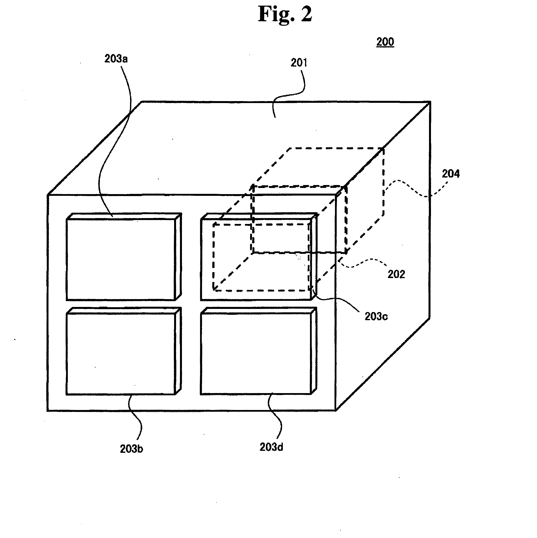
[0015]A test chamber apparatus according to an aspect of embodiments of the present invention comprises a depressurized space in which a test subject device to be tested by a test device is placed, a board fixed as a part of a wall for defining the depressurized space, a terminal formed on a surface of the board exposed to the depressurized space for transmitting signals between the test device and the test subject device, and a terminal formed on an opposite surface to the surface exposed to the depressurized space for transmitting signals between the test device and the test subject device. This achieves to maintain the sealing capability in the depressurized space and to accurately control air pressure in the depressurized space.

[0016]The board may be detachably fixed to the wall for defining...


PUM


Abstract

Embodiments of the present invention help to maintain the sealing capability of a depressurized space where a test subject device is placed in a test chamber apparatus, and to accurately control air pressure in the depressurized space. In one embodiment of the present invention, a depressurized space and a separate space are separated by a connection board. The connection board transmits signals between a test computer and an HDD. The connection board is fixed to an inner wall defining the depressurized space and the separate space. An opening is formed on the inner wall. The connection board which is larger than the opening covers the opening. To maintain the air sealing property in the depressurized space, the connection board is fixed to the inner wall via a gasket.

Description

CROSS-REFERENCES TO RELATED APPLICATIONS[0001]The instant nonprovisional patent application claims priority to Japanese Patent Application No. 2007-000585 filed Jan. 5, 2007 and which is incorporated by reference in its entirety herein for all purposes.BACKGROUND OF THE INVENTION[0002]Data storage devices using various kinds of media, such as optical disks and magnetic tape, have been known in the art. In particular, a hard disk drive (HDD) has been widely used as a storage device of a computer and has been a storage device for current computer systems. Moreover, the HDD has found widespread application such as a removable memory used in a moving image recording / reproducing apparatus, a car navigation system, a cellular phone, or a digital camera, as well as the computer system, due to its outstanding characteristics.[0003]An HDD comprises a magnetic disk for storing data and a head slider for accessing the magnetic disk. The head slider comprises a head element portion for reading ...

Claims


Application Information

Patent Timeline
Patent Type & Authority Applications(United States)
IPC IPC(8): G01R1/04
CPCG01R31/2849
Inventor KUWASHIMA, MASAKITAKEDA, NOBUOTSUYAMA, MASASHINISHIUCHI, SHIGETO
Owner HITACHI GLOBAL STORAGE TECH NETHERLANDS BV
Learn More