
Electrical terminal

a technology of electric terminals and terminals, applied in the direction of coupling device connections, sustainable manufacturing/processing, final product manufacturing, etc., can solve the problems of increasing costs, difficult freezing of solder, and prone to breakage, and achieve the effect of preventing problems

Inactive Publication Date: 2008-07-03
LOTES
View PDF3 Cites 5 Cited by
  • Summary
  • Abstract
  • Description
  • Claims
  • Application Information

AI Technical Summary

Benefits of technology

[0010]An object of the present invention is to provide an electrical terminal, which can fix the solder in order to prevent the problems caused by repetitive welding.
[0012]Compared to the prior art, the present invention grips the solder within the welding portion thereby decreasing the amount of impurities that become interfused in the soldering fluid, thereby avoiding the soldering fluid of the electrical terminals from blending with each other when the solder is welded onto the printed circuit board. Therefore the solder is kept clear and increases the quality of the electrical connection and strengthens the welding bond.

Problems solved by technology

Due to the twice welding process, the soldering fluid of the adjacent terminals after heating often blend together, thereby causing manufacturing defect and increasing costs.
Because the welding process has been performed many times, many impurities are interfused in the solder, which makes the solder difficult to freeze and apt to break.

Method used


Image

  • Electrical terminal
  • Electrical terminal
  • Electrical terminal

Examples


Embodiment Construction

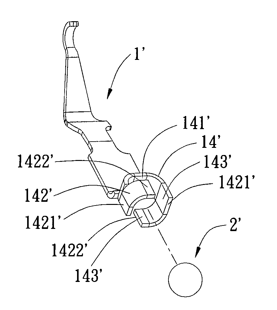
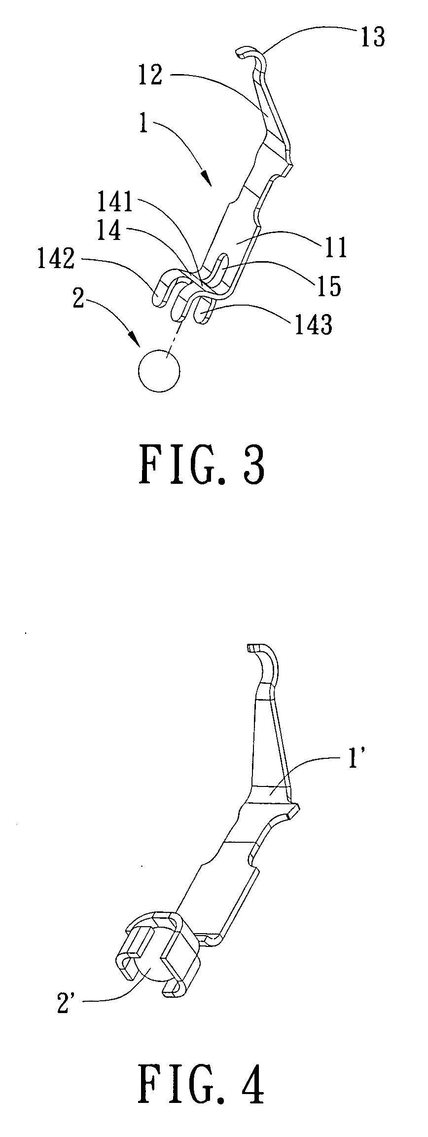
[0021]With reference to FIGS. 1 to 3, the present invention provides an electrical terminal 1 disposed on the IC socket (omitted in the drawing) for connecting with the printed circuit board (omitted in the drawing).

[0022]The electrical terminal 1 includes a body 11, an elastic arm 12 and a welding portion 14. The elastic arm 12 extends upwardly obliquely from the body 11. The end of the elastic arm 12 has a contact 13 disposed thereon. The welding portion 14 extends downwardly from the body 11.

[0023]The welding portion 14 includes a baffle 141 and three gripping pieces 142. The baffle 141 extends from the underside of the body 11 and abuts against a solder 2. The solder 2 can be a tin ball. The three gripping pieces 142 extend respectively from the two sides of baffle 141 for gripping the solder 2. Each gripping piece 142 has at least one gripping portion 143. That is, the three gripping pieces 142 have at least three gripping portions 143 for gripping the solder 2. The underside o...


PUM


Abstract

An electrical terminal for gripping a solder includes a body, an elastic arm extending from the body, which has a contact at the end of the elastic arm, and a welding portion extending downwardly from the body, wherein the welding portion includes a baffle and at least two gripping pieces, the baffle extends from the underside of the body and abuts against the solder, and the gripping pieces extend bendly from the baffle and grip the solder. The present invention ensures the solder is gripped within the welding portion in order to decrease the amount of impurities interfused in the soldering fluid, and prevents the soldering fluid of the electrical terminals from blending with each other when the solder is welded on the printed circuit board. Therefore the solder is kept clear to improve the quality of the electrical connection and strengthen the welding bond.

Description

BACKGROUND OF THE INVENTION[0001]1. Field of the Invention[0002]The present invention relates to an electrical terminal.[0003]2. Description of Prior Art[0004]An electrical connector is connected with a CPU and a PCB (printed circuit board). In general, there are two kinds of structures for electrical connectors, one which uses an inserting pin and another which uses a surface mounted terminal. As manufacturing techniques have developed rapidly over recent years, the planting ball technique has become more commonly used throughout the connector industry to put the surface mounted terminal in widespread use.[0005]Two Chinese patents (No: 03205304.5 and No: 01280419.3) disclose a structure for the planting ball of a connector. The present structure is to weld the solder at the end of the terminal via heating the solder.[0006]The prior arts described above suffer from the following defect:[0007]The solder is first fixed through a welding process at the end of the terminal. It is then n...

Claims


Application Information

Patent Timeline
IPC IPC(8): H01R13/631H01R12/55
CPCH01R4/02H01R12/57H01R13/24H05K2203/041H05K2201/10189H05K2201/10984H05K3/3426Y02P70/50
Inventor DENG, LIMIN
Owner LOTES
Learn More