
Plastic coated edge structure used for portable electronic device and method for making the same

a technology of plastic material and edge structure, which is applied in the field of plastic coated edge structure and methods for making the same, can solve the problems of melted plastic material being prone to solidification and prone to rapid solidification, and the plastic material will not adequately coat the fringe portion of the metallic sh

Inactive Publication Date: 2008-07-03
HONG FU JIN PRECISION IND (SHENZHEN) CO LTD +1
View PDF5 Cites 32 Cited by
  • Summary
  • Abstract
  • Description
  • Claims
  • Application Information

AI Technical Summary

Benefits of technology

[0008]In another aspect, a method for making the plastic coated edge structure includes: providing a base sheet including a fringe portion, and the fringe portion defining a plurality of though holes; putting the base sheet into an injection mold; injecting a melted plastic material into the injection mold from a side of the fringe portion of the base sheet to an opposite side of the fringe portion of the base sheet from the through holes to form a protective plastic layer for coating the fringe portion of the base sheet; solidifying the plastic material to form the plastic coated edge structure; and taking the plastic coated edge structure out of the injection mold.

Problems solved by technology

However, the melted plastic material is prone to solidify quickly and an injection path from the exterior side of the fringe portion of the metallic sheet to the opposite inner side of the fringe portion of the metallic sheet is relatively long, and if the plastic layer is very thin, the plastic material will not adequately coat the fringe portion of the metallic sheet.

Method used


Image

  • Plastic coated edge structure used for portable electronic device and method for making the same
  • Plastic coated edge structure used for portable electronic device and method for making the same
  • Plastic coated edge structure used for portable electronic device and method for making the same

Examples


Embodiment Construction

[0021]Reference will now be made to the drawings to describe preferred embodiments of the present plastic coated edge structure in detail.

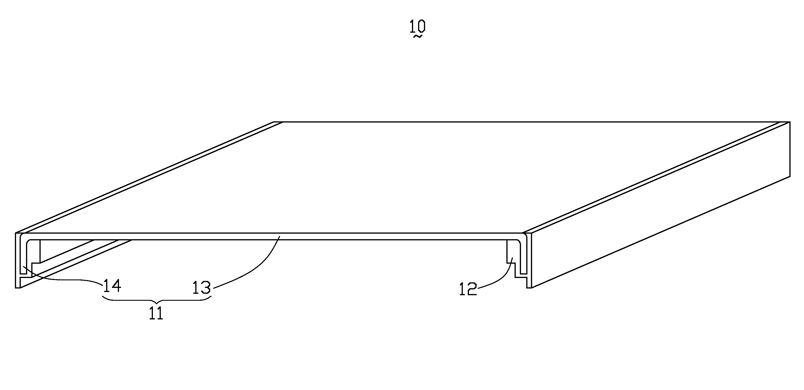
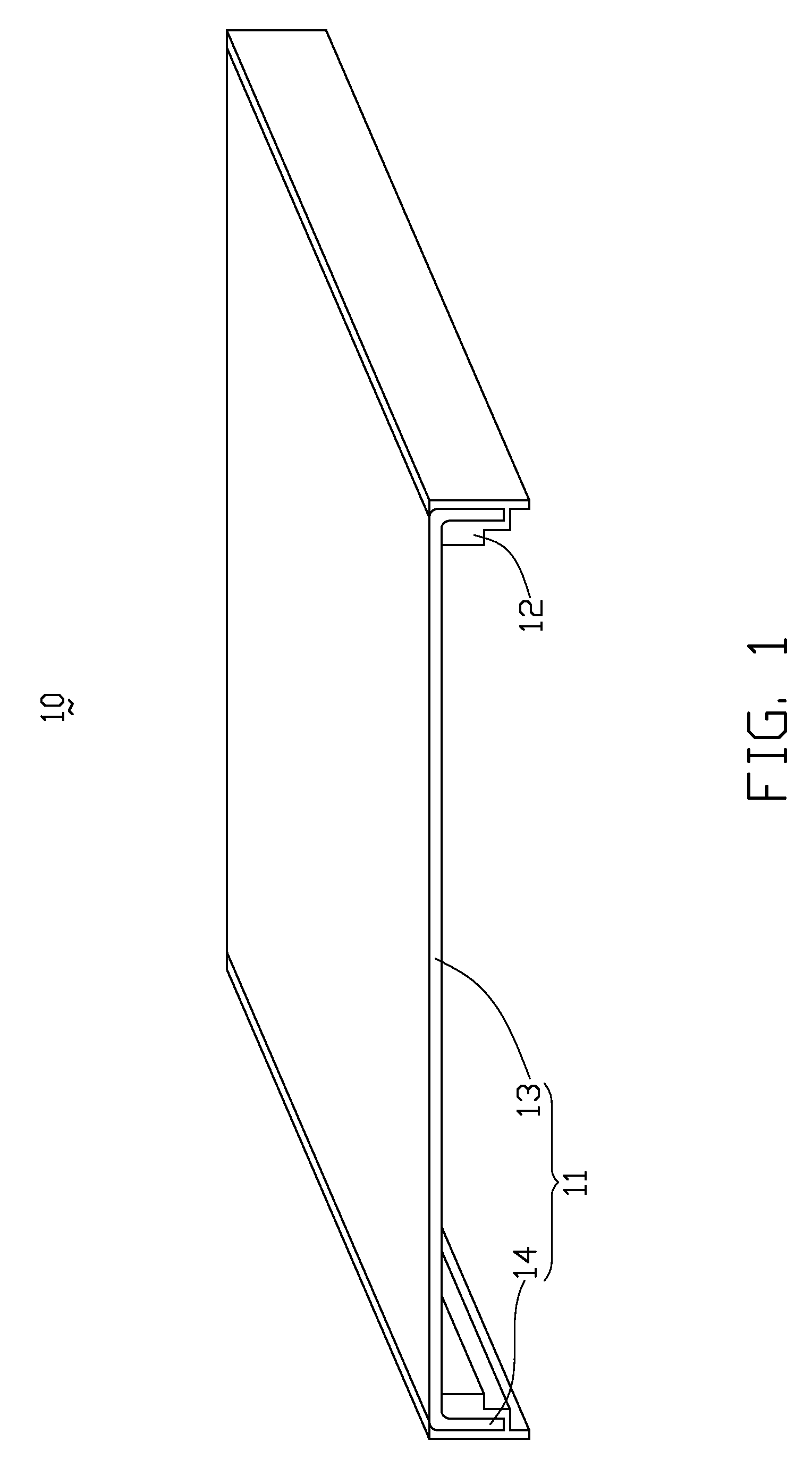
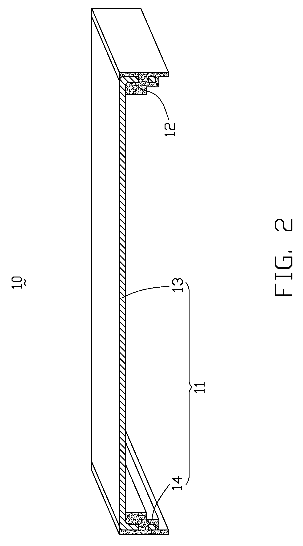
[0022]Referring to FIGS. 1 through 3, a plastic coated edge structure 10 used for portable electronic devices such as mobile phones and personal digital assistants (PDAs) in accordance with a first preferred embodiment is shown. The plastic coated edge structure 10 includes a base sheet 11 and at least one protective plastic layer 12 that coats a part of the base sheet 11. The base sheet 11 includes a main body 13 and at least one fringe portion 14. In this embodiment, the fringe portion 14 includes two sidewalls perpendicularly extending from opposite sides of the main body 13 correspondingly. The sidewalls are coated with the protective layer 12. Each of the sidewalls defines a plurality of through holes 15, and a part of the protective plastic layer 12 engages in the through holes 15. The through holes 15 are oblong circular holes and are defin...


PUM

PropertyMeasurementUnit
Metallic bondaaaaaaaaaa

Abstract

An exemplary plastic coated edge structure (10) includes a base sheet (11) and a protective plastic layer (12). A fringe portion of the base sheet defines a plurality of through holes (15). The protective plastic layer coats the fringe portion, and part of the protective plastic layer engages in the through holes. A method for making a plastic coated edge structure includes: providing a base sheet including a fringe portion, the fringe portion defining a plurality of though holes; putting the base sheet into an injection mold; injecting a melted plastic material into the injection mold from a side of the fringe portion to an opposite side of the fringe portion from the through holes to form the protective plastic layer for coating the fringe portion; solidifying the plastic material to form a plastic coated edge structure; and taking the plastic coated edge structure out of the injection mold.

Description

BACKGROUND OF THE INVENTION[0001]1. Field of the Invention[0002]The present invention generally relates to plastic coated edge structures and methods for making the same, and more particularly, to a plastic coated edge structure used for a portable electronic device.[0003]2. Discussion of the Related Art[0004]Presently, portable electronic devices such as mobile phones and personal digital assistants (PDAs) generally include a plurality of metallic components that includes metallic sheets. The metallic sheets are generally very thin. A plastic layer is applied to coat a fringe portion of the metallic sheet so as to form a plastic coated edge structure. The plastic coated edge structure has a high physical strength and can further prevent the fringe portion of the metallic sheet from damages and / or causing injuries.[0005]Typically, a method for forming the plastic coated edge structure, a melted plastic material is injected from an exterior side of the metallic sheet to an opposite i...

Claims


Application Information

Patent Timeline
IPC IPC(8): B32B3/10B29C45/14
CPCB29C45/14344B29C2045/14368Y10T428/24331B29C2045/14327B29L2031/3437
Inventor LIU, WEN-QUANFAN, WEI-JIEHE, XIFU, LIAO-HUA
Owner HONG FU JIN PRECISION IND (SHENZHEN) CO LTD
Learn More