
Adaptive Video Telephone System

a video telephone system and adaptive technology, applied in the field of video telephone systems, can solve the problems of one or more future pictures not being correctly decoded, and achieve the effects of eliminating jitter, high resolution video transmission, and high quality video images and sound

Inactive Publication Date: 2008-07-03
HUBLINK LLC
View PDF4 Cites 26 Cited by
  • Summary
  • Abstract
  • Description
  • Claims
  • Application Information

AI Technical Summary

Benefits of technology

[0009]In accordance with the present invention, a videophone system is provided in which high resolution video transmission between videophones is achieved. Compressed video signals and audio signals may be transmitted through any communications network, with the system providing real time adaptive error recovery and synchronization between the audio and video signals to produce high quality video images and sound. The system is highly resilient, adapting in real time to changing conditions in a network or to network errors due to data corruption or loss that can be produced, for example, by noise or line losses, thereby substantially eliminating jitter, signal packet loss or delay, or other errors which produce signal degradation.
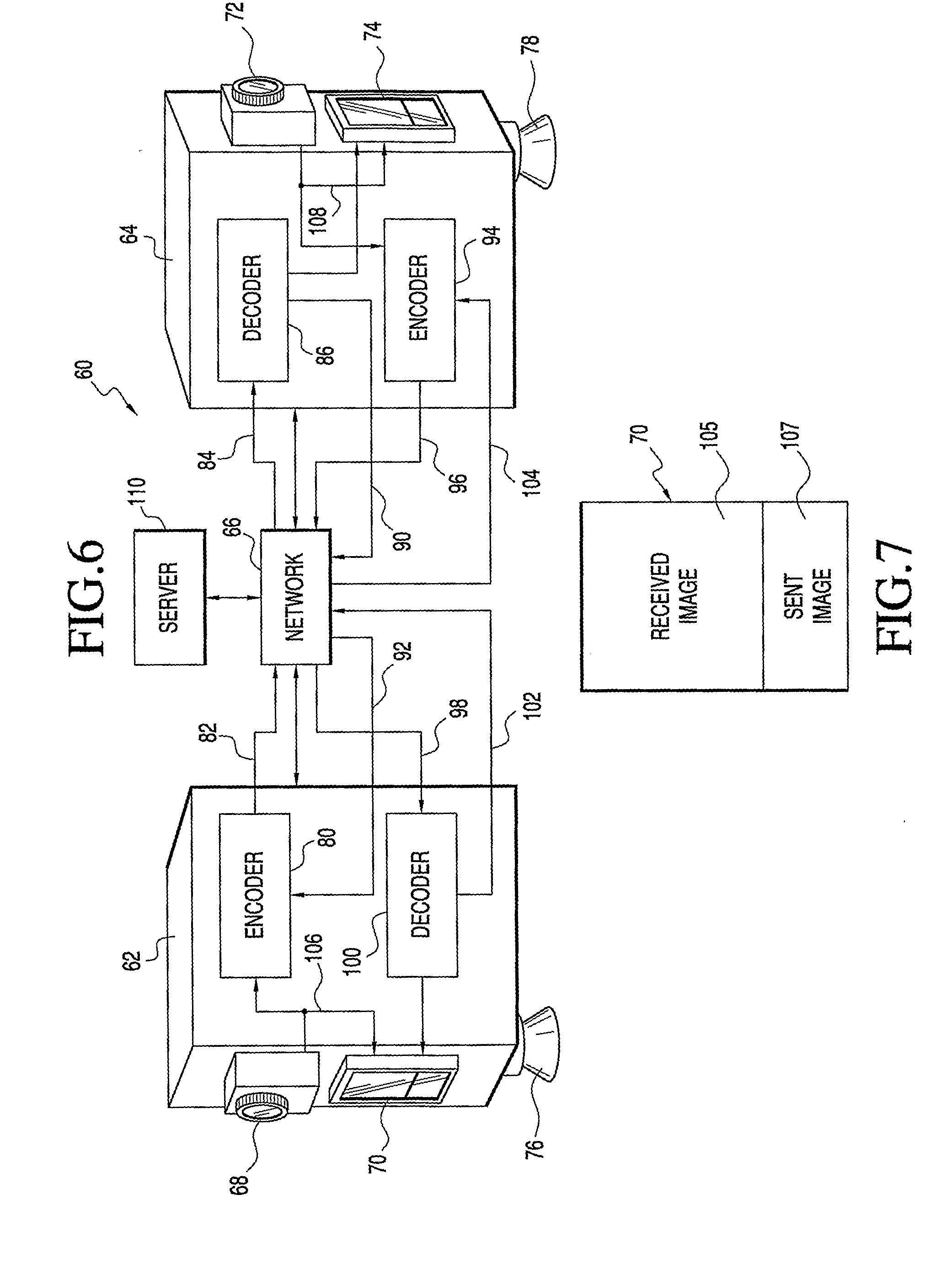
[0010]A videophone system may consist of a video source at one end and a video display at the other, connected by a medium that may be lossy, and may operate using an encoding technique in which data representing current video may depend on earlier pictures in the video. An example of such a system would be a pair of videophones, each with a camera and a display that shows video from the other phone, encoded using the standard video compression technique known as H.264, but connected by an unreliable network. The present invention provides ways to increase the quality and reliability of such a system.

Problems solved by technology

If a reference slice is lost or damaged, then one or more future pictures cannot be correctly decoded.

Method used


Image

  • Adaptive Video Telephone System
  • Adaptive Video Telephone System
  • Adaptive Video Telephone System

Examples


Embodiment Construction

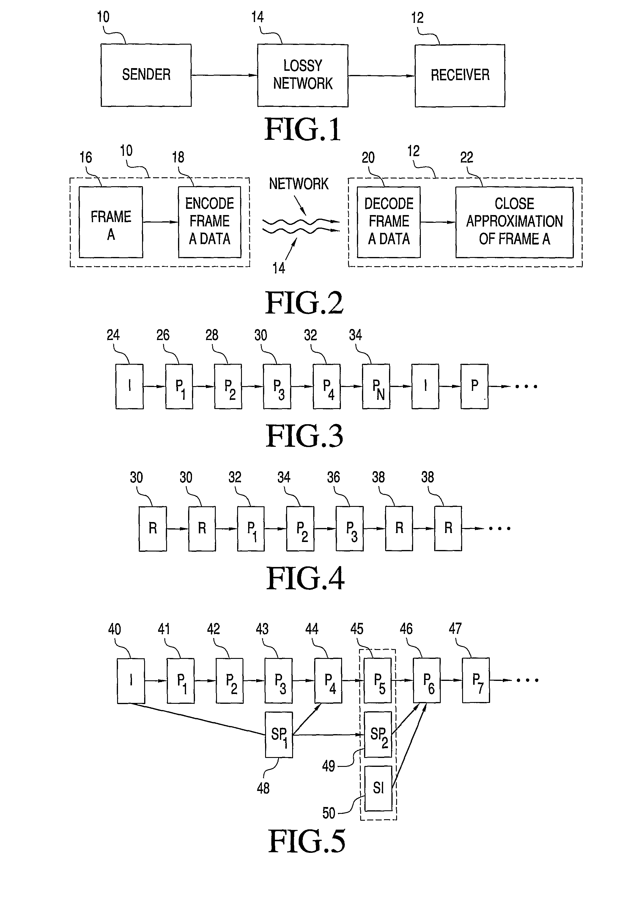
[0036]Turning now to a more detailed description of the invention, there is illustrated in FIG. 1 in block diagram form a simplified version of a videophone system in which a first videophone 10 is activated to send a video and audio signal to a receiver 12 by way of a network 14, which may incorporate any desired communications path such as cable, a wireless network, or the like. The receiver 12 preferably is also a videophone capable of transmitting video and audio signals to be received by videophone 10. Any number of videophones may be connected to the network, as is well known.

[0037]It is expected that network 14 usually will not be ideal, and will introduce delays or noise, or will otherwise corrupt data being transmitted, resulting in degraded images and loss of synchronization between transmitted audio and video signals. A primary feature of the present invention is the provision of real time correction of corrupted or lost data to produce high-resolution video images synchr...


PUM


Abstract

A videophone system providing high resolution video transmission between videophones utilizes compressed video signals and audio signals which may be transmitted through any communications network, with the system providing real time adaptive error recovery and synchronization between the audio and video signals to produce high quality video images and sound. The system is highly resilient, adapting in real time to changing conditions in a network or to network errors due to data corruption or loss that can be produced, for example, by noise or line losses, thereby substantially eliminating fitter, signal packet loss or delay, or other errors which produce signal degradation.

Description

FIELD OF THE INVENTION[0001]The present invention relates, in general, to video telephone systems for transmitting compressed video data over a network, and more particularly to adaptive systems for real time network error recovery for high quality video telephone communications.BACKGROUND OF THE INVENTION[0002]Traditionally, telephone and video communication systems have been bifurcated. Conventional telephone systems (or PSTN systems) operate at a bandwidth appropriate for voice communications, and typically provide spontaneous, point-to-point communications, such as two-way voice and data services, between two end users. In contrast, video distribution networks (including cable television systems), operate at a much broader bandwidth than telephone systems, and are usually employed to transmit pre-determined, high quality, full-motion video and audio concurrently to a plurality of subscribers.[0003]It has long been felt that if the best features of voice and video communication s...

Claims


Application Information

Patent Timeline
IPC IPC(8): H04N7/14
CPCH04N19/115H04N19/61H04N19/137H04N19/89H04N19/17H04N19/65H04N19/166
Inventor KRISBERGH, HAL M.AUGENBRAUN, JOSEPH E.JESUP, RANDELL E.REAVY, MAIRE D.GORT, RANDALL J.KANNAN, NAVNEETHBLACKMON, WHITNEY D.WESTERFER, RICHARD E.WACHOB, DAVID E.
Owner HUBLINK LLC
Learn More