
Plasma display device

a technology of a display device and a plasma, which is applied in the field of plasma display devices, can solve the problems of increasing the cost of implementing a plasma display device and increasing the power consumption, and achieve the effect of reducing the heat produced by the driving circui

Inactive Publication Date: 2008-07-03
SAMSUNG SDI CO LTD
View PDF0 Cites 2 Cited by
  • Summary
  • Abstract
  • Description
  • Claims
  • Application Information

AI Technical Summary

Benefits of technology

[0017]An aspect of the present invention is directed to providing a plasma display device, wherein a level of heat produced by a driving circuit is reduced.
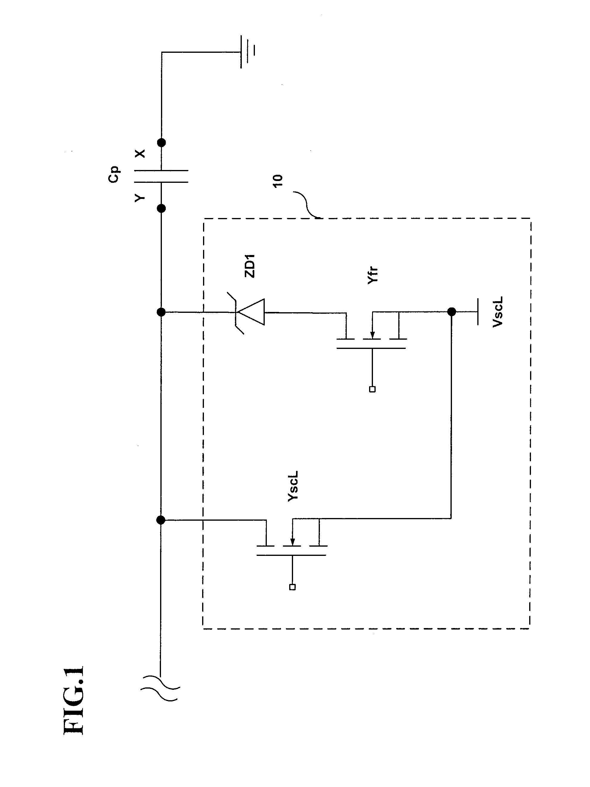
[0019]According to another exemplary embodiment of the present invention, a plasma display device includes: a plurality of first electrodes; and a first driving unit for applying a scan voltage to each of the first electrodes in an address period. The first driving unit includes: a first diode having an anode coupled to each of the first electrodes; and a first switch having a first terminal coupled to a cathode of the first diode and a second terminal coupled to a first power source for supplying the scan voltage. The first diode is adapted to hinder a current flow from the first power source to each of the first electrodes.

Problems solved by technology

Further, since the voltage VscL is approximately −200 V, and ΔV is approximately 25 V, the Zener diode ZD1 has a large withstand voltage of approximately 175 V. However, the use of a Zener diode having a large withstand voltage is accompanied by an increase in costs for implementing a plasma display device and an increase in power consumption.

Method used


Image

  • Plasma display device
  • Plasma display device
  • Plasma display device

Examples


Embodiment Construction

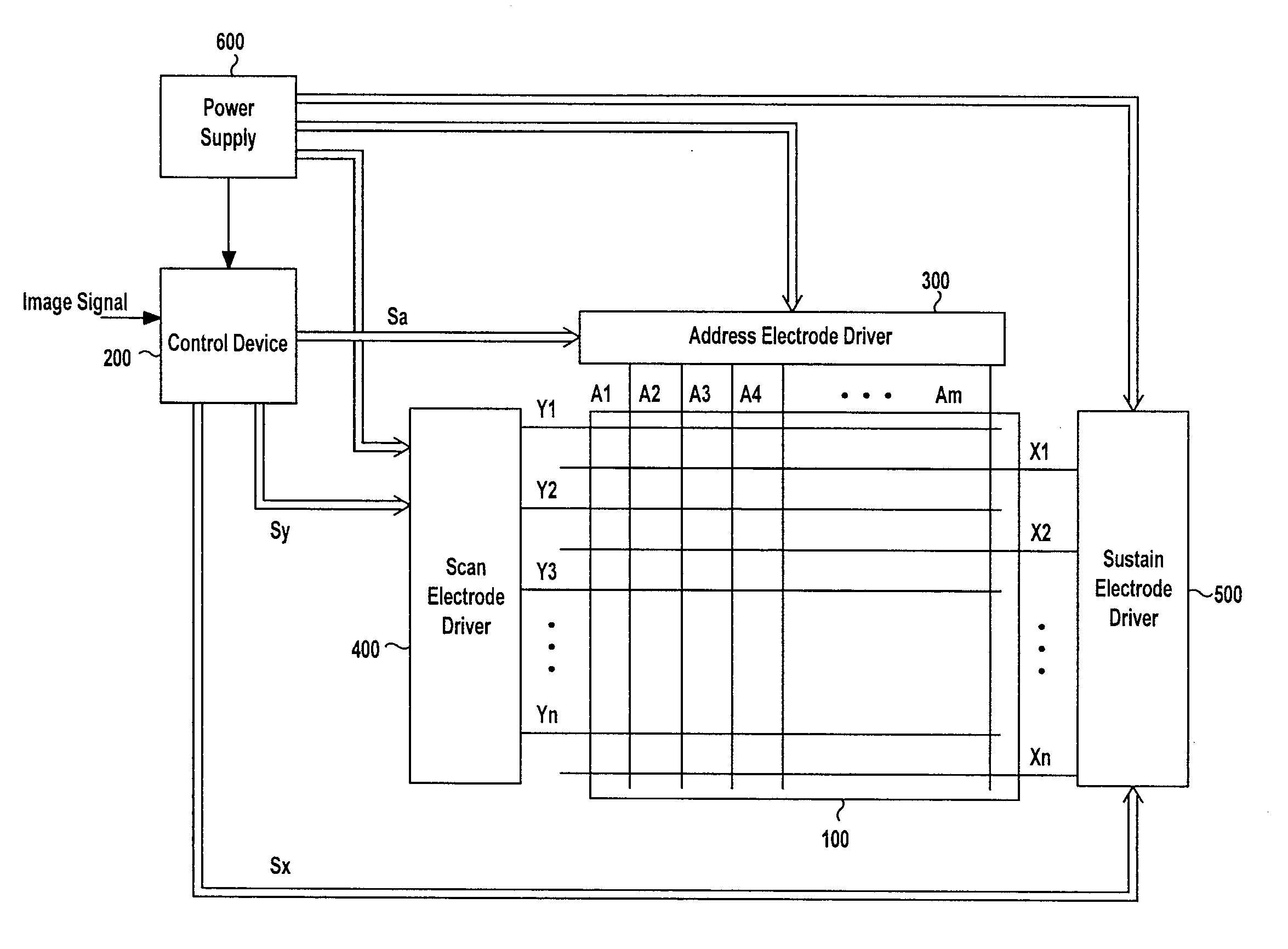
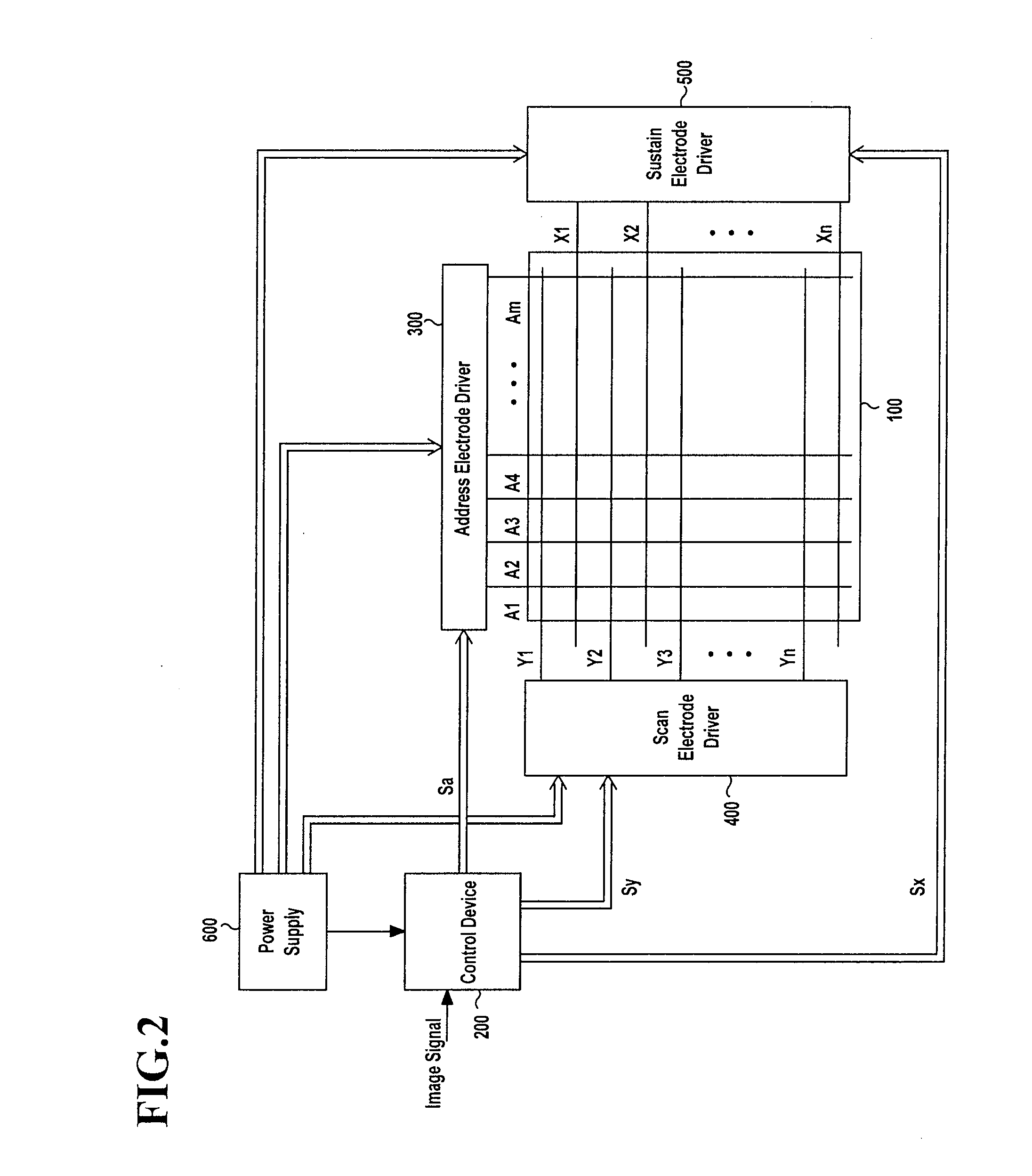
[0024]In the following detailed description, only certain exemplary embodiments of the present invention have been shown and described, simply by way of illustration. As those skilled in the art would realize, the described embodiments may be modified in various different ways, all without departing from the spirit or scope of the present invention. Accordingly, the drawings and description are to be regarded as illustrative in nature and not restrictive. Like reference numerals designate like elements throughout the specification.

[0025]Throughout this specification and the claims that follow, when it is described that a first element is “coupled” to a second element, the first element may be “directly coupled” to the second element or “electrically coupled” to the second element through one or more other elements. In addition, unless explicitly described to the contrary, the word “comprise” and variations such as “comprises” or “comprising”, will be understood to imply the inclusio...


PUM


Abstract

A plasma display device includes: a plasma display panel including first and second electrodes and third electrodes crossing the first and second electrodes; a power supply for receiving an input voltage and generating a first voltage using the input voltage; and a first driving unit for applying an output voltage to each of the first electrodes. The output voltage falls gradually from a second voltage higher than the first voltage to the first voltage during a reset period. The first driving unit includes: a first diode having an anode coupled to each of the first electrodes; and a first switch having a first terminal coupled to a cathode of the first diode and a second terminal coupled to a first power source for supplying the first voltage. A voltage of each of the first electrodes falls to the first voltage when the first switch is in a turned-on state.

Description

CROSS-REFERENCE TO RELATED APPLICATION[0001]This application claims priority to and the benefit of Korean Patent Application No. 10-2007-0000111, filed in the Korean Intellectual Property Office on Jan. 2, 2007, the entire content of which is incorporated herein by reference.BACKGROUND OF THE INVENTION[0002]1. Field of the Invention[0003]The present invention relates to a plasma display device.[0004]2. Description of the Related Art[0005]A plasma display device is a device that displays characters or images using plasma generated by gas discharge. Depending on its size, a plasma display panel (PDP) may include more than hundreds of thousands to millions of discharge cells arranged in a matrix shape.[0006]In general, the plasma display device is driven during frames of time. Each frame is divided into a plurality of subfields each having a brightness weight value. Gray levels of a discharge cell in the PDP may be expressed by a combination of the brightness weight values of subfields...

Claims


Application Information

Patent Timeline
Patent Type & Authority Applications(United States)
IPC IPC(8): G09G3/28G09G3/291G09G3/20G09G3/288G09G3/292G09G3/293G09G3/294G09G3/296G09G3/298H04N5/66
CPCG09G3/293G09G2330/028G09G2330/021G09G3/296
Inventor LEE, SUNG-SU
Owner SAMSUNG SDI CO LTD
Learn More