Wheel suspennsion for a motor vehicle

Inactive Publication Date: 2008-07-03
THYSSENKRUPP BILSTEIN +1
View PDF3 Cites 7 Cited by
  • Summary
  • Abstract
  • Description
  • Claims
  • Application Information

AI Technical Summary

Benefits of technology

[0009]Against this background, it is an object of the invention to provide a wheel suspension for a motor vehicle, having the characteristics described initially, which demonstrates improved damping behavior. In particular, it is an object to make possible precise adjustment of the body spring, in a simple manner.
[0011]The spring rate of the body spring results from the demands on the wheel suspension. The spring rate of the stress relief spring can be freely selected, to a great extent. The additional damping element supports both the body spring and the electromechanical actuator during high-frequency and low-frequency vibrations. In this way, the entire damping behavior is clearly improved and only slight setting forces and setting paths of the actuator are typically necessary for active vibration compensation. The electromechanical actuator can be controlled directly by a control and regulation device, so that the wheel suspension is characterized by a comparatively simple structure.
[0012]Because an interposition of a hydraulic system with feed lines and various hydraulic components is eliminated, in particular, a rapid and direct transfer of force from the actuator to the body spring can be guaranteed. In particular, the electromechanical actuator can easily demonstrate rigidity, thereby making a precise and clearly defined rotation of the body spring possible. The wheel height level of a wheel of a motor vehicle disposed on the transverse control arm can be kept constant via a rotation of the body spring by the electromechanical actuator, independent of the static forces due to the weight stress of the wheel suspension and the dynamic forces acting on the wheel suspension, for example due to an uneven road surface or driving maneuvers. She wheel suspension according to the invention furthermore allows regulation of the wheel height as a function of the speed, or as a function of the requirements of an increase in ground clearance. Production tolerances of the body spring and optionally provided additional spring elements can also be balanced out via the adjustment possibilities provided by the electromechanical actuator.
[0013]In one embodiment, the wheel suspension has only the body spring and optionally additional torsion bar springs. This embodiment has a low space requirement. In particular, the construction space in the area of a wheel case can be minimized because it is no longer necessary to dispose a conventional suspension strut there. In particular, the available width of a trunk space or engine space disposed above a vehicle axle can be increased by means of the elimination of suspension strut domes, in comparison with a conventional embodiment in which suspension struts are provided.
[0017]In a particularly preferred embodiment, the second end of the body spring and an assigned end of the stress relief spring are coupled by way of a setting element, whereby the setting element allows rotation of the ends assigned to one another, for adjustment. The connection by way of the setting element allows balancing out production tolerances of the torsion bar springs, for example. Furthermore, the adjustment between the stress relief spring and the body spring allows an adaptation to different stresses, and a displacement of the design position, so that the wheel suspension can be adapted to different curb weights of different vehicle types, for example.

Problems solved by technology

The known system for active vibration compensation, in which a hydraulic adjustment device is connected with a hydraulic source by way of hydraulic lines and with the interposition of a controllable regulation and setting element, is technically complicated.
This rigidity is difficult to achieve with a hydraulic system.

Method used


Image

  • Wheel suspennsion for a motor vehicle
  • Wheel suspennsion for a motor vehicle
  • Wheel suspennsion for a motor vehicle

Examples


Embodiment Construction

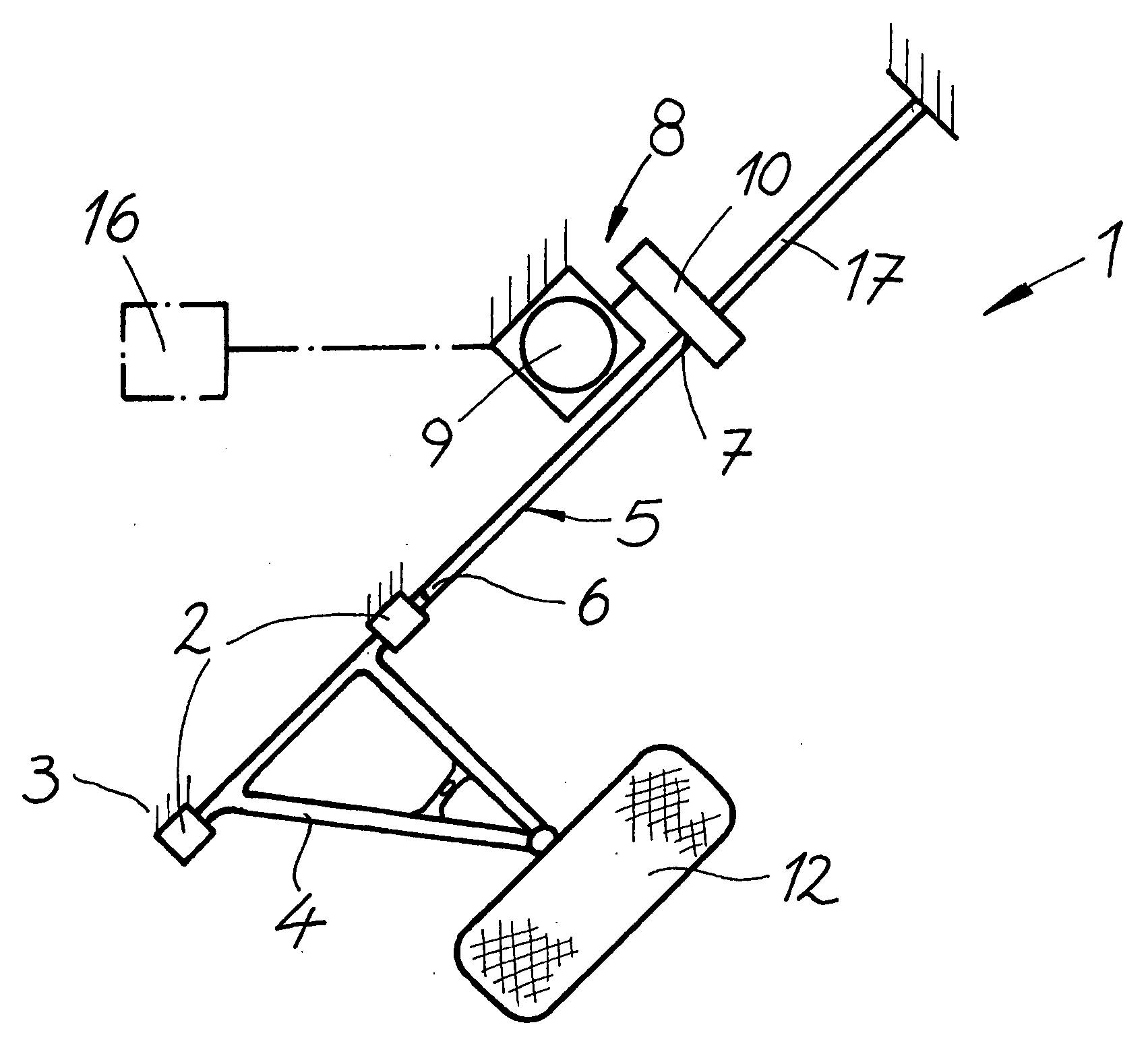
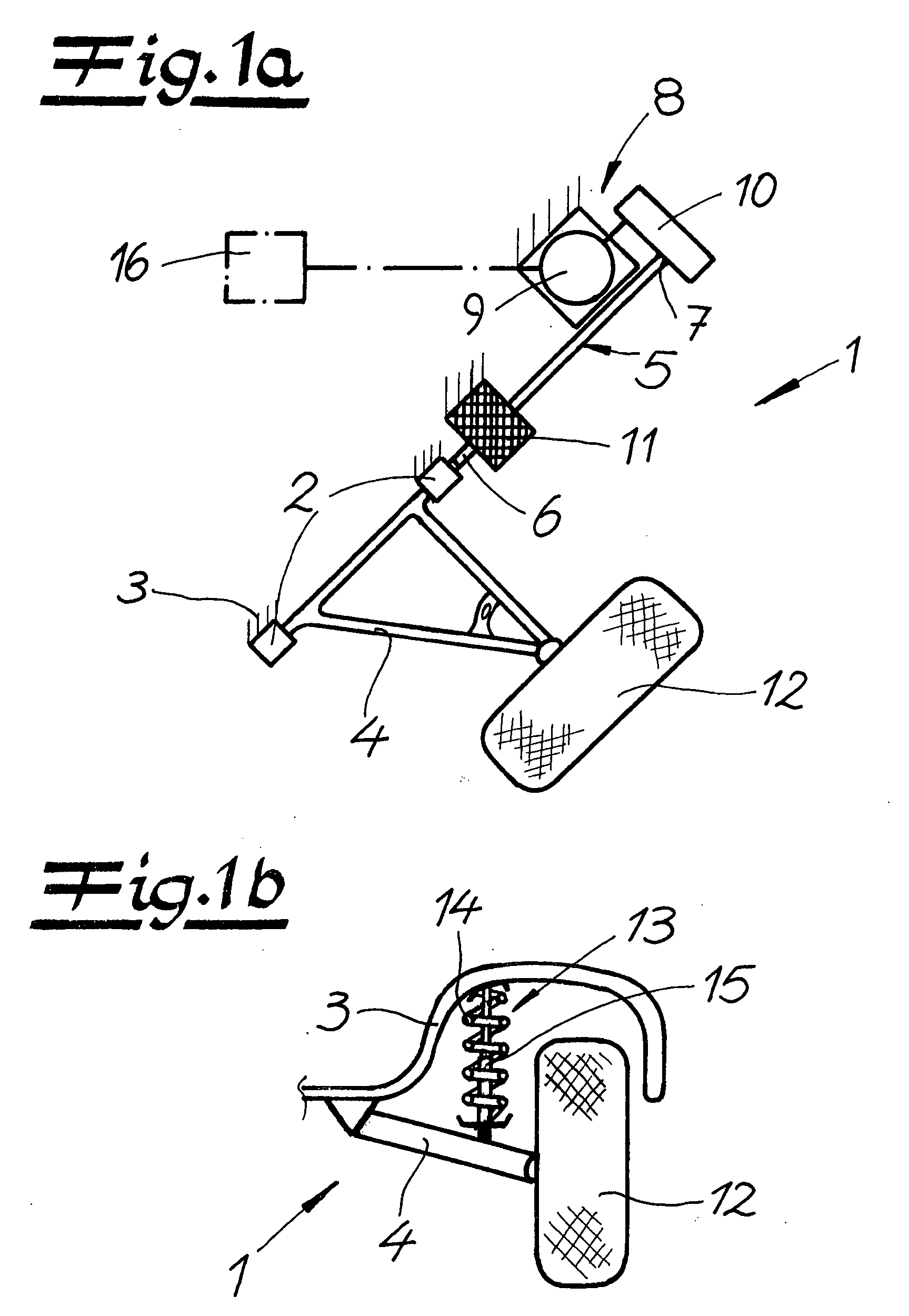
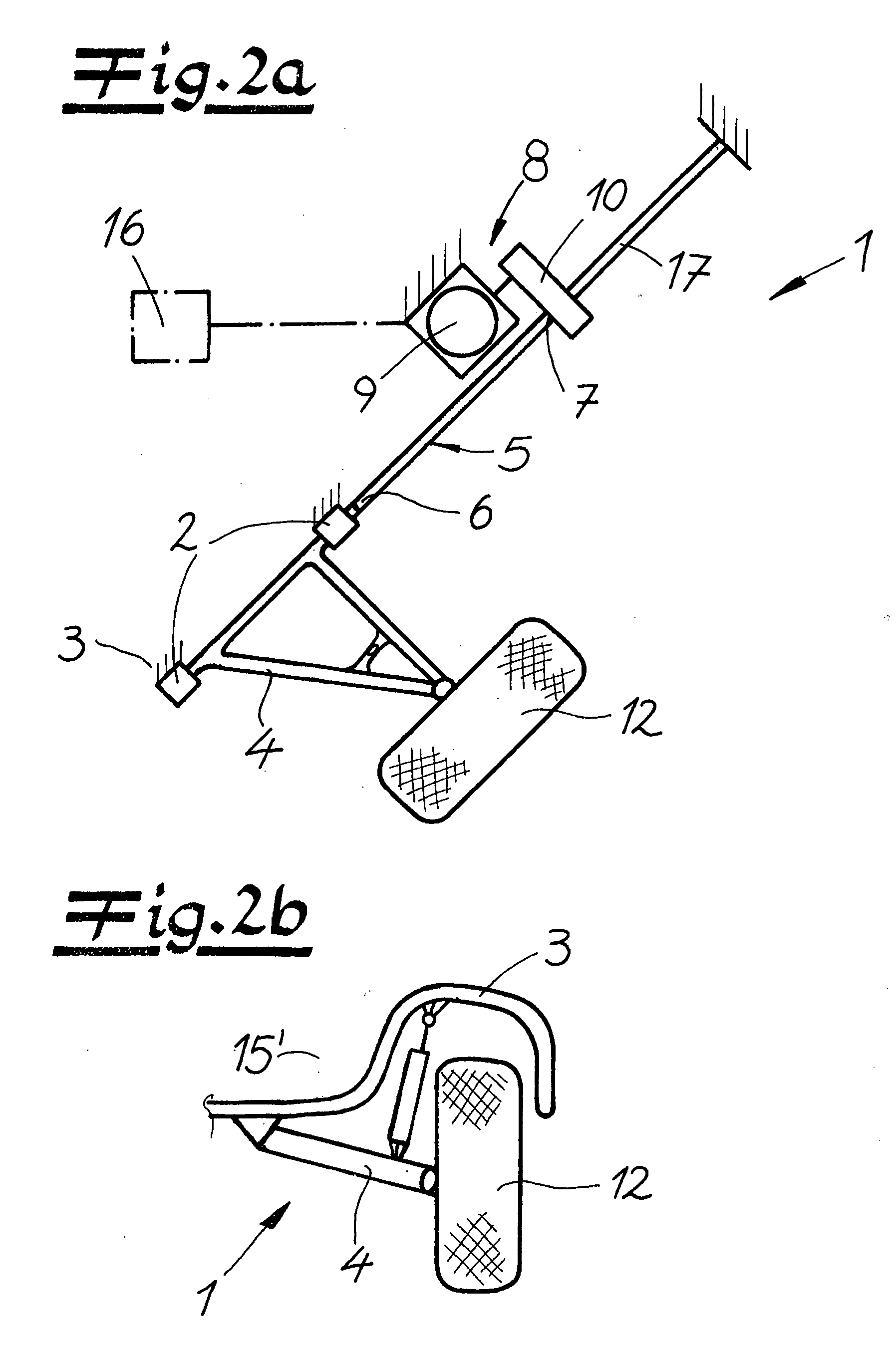
[0029]Turning now in detail to the drawings, FIG. 1a shows the fundamental structure of a wheel suspension 1 for a motor vehicle, having a transverse control arm 4 that can be attached to a vehicle body 3 by way of bearings 2 and can be rotated about a longitudinal axis, and having a body spring 5 configured as a tubular torsion bar for absorbing rotational movements of transverse control arm 4 around the longitudinal axis. The body spring is disposed on transverse control arm 4 so as to rotate with it, with a first end 6. At a second end 7 of body spring 5, an actuator 8 is disposed, made up of a servomotor 9 and a step-down gear mechanism 10 that acts on body spring 5, to adjust the angle of rotation of body spring 5. Close to transverse control arm 4, a passive rotation damper 11 is provided as a damping element, which connects body spring 5 with vehicle body 3. A vehicle wheel 12 is disposed on transverse control arm 4.

[0030]FIG. 1b shows the assembly according to FIG. 1a in a v...


PUM


Abstract

A wheel suspension for a motor vehicle has a transverse control arm that can be attached to a vehicle body by way of bearings and can be rotated about a longitudinal axis, and a body spring configured as a torsion bar spring for absorbing rotational movements of the transverse control arm about the longitudinal axis. The body spring is disposed on the transverse control arm so as to rotate with it, with a first end. An electromechanical actuator for changing the angle of rotation of the body spring is disposed at a second end of the body spring. The wheel suspension has a damping element. The second end of the body spring is connected with a stress relief spring that is configured as a torsion bar spring, disposed coaxially with the body spring, and can be attached to the vehicle body.

Description

CROSS REFERENCE TO RELATED APPLICATIONS[0001]Applicants claim priority under 35 U.S.C. §119 of German Application No. 10 2006 061 985.4 filed Dec. 21, 2006.BACKGROUND OF THE INVENTION[0002]1. Field of the Invention[0003]The present invention relates to a wheel suspension for a motor vehicle, having a transverse control arm that can be attached to a vehicle body by way of bearings and can be rotated about a longitudinal axis, and having a body spring configured as a torsion bar spring, for absorbing rotational movements of the transverse control arm about the longitudinal axis. The body spring is disposed on the transverse control arm so as to rotate with it, with a first end. An electromechanical actuator for changing the angle of rotation of the body spring is disposed at a second end of the body spring. The wheel suspension is particularly provided as a single-wheel suspension, on at least one axle of a passenger car or a utility vehicle.[0004]2. The Prior Art[0005]A wheel suspens...

Claims


Application Information

Patent Timeline
IPC IPC(8): B60G11/18
CPCB60G11/181B60G11/20B60G17/025B60G2200/14B60G2204/4191B60G2202/42B60G2204/122B60G2500/20B60G2204/419B60G2202/132
Inventor PREUKSCHAT, ALFREDBRENDECKE, THOMASMILLER, LUITPOLDELLMANN, SIEGFRIED
Owner THYSSENKRUPP BILSTEIN
Why Eureka
Try Eureka