
Machine for labeling containers

Inactive Publication Date: 2008-07-03
KRONES AG
View PDF22 Cites 17 Cited by
  • Summary
  • Abstract
  • Description
  • Claims
  • Application Information

AI Technical Summary

Benefits of technology

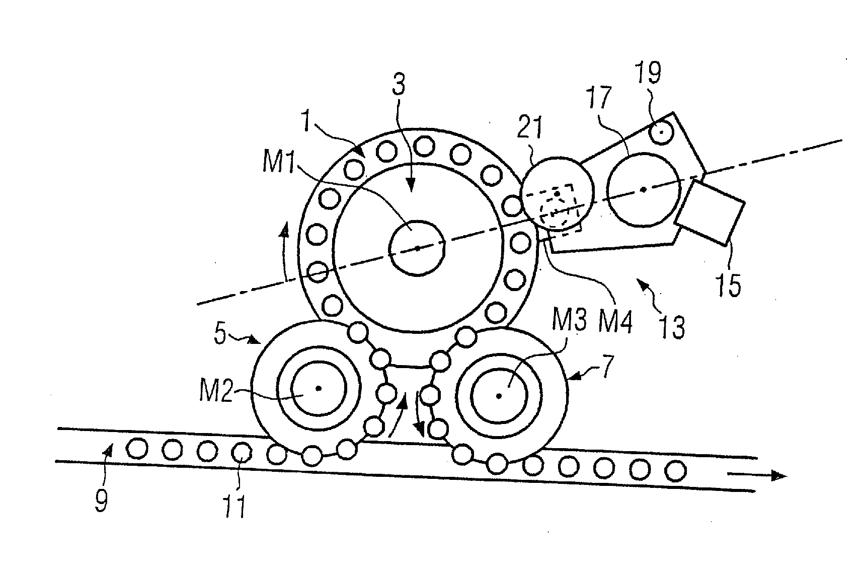
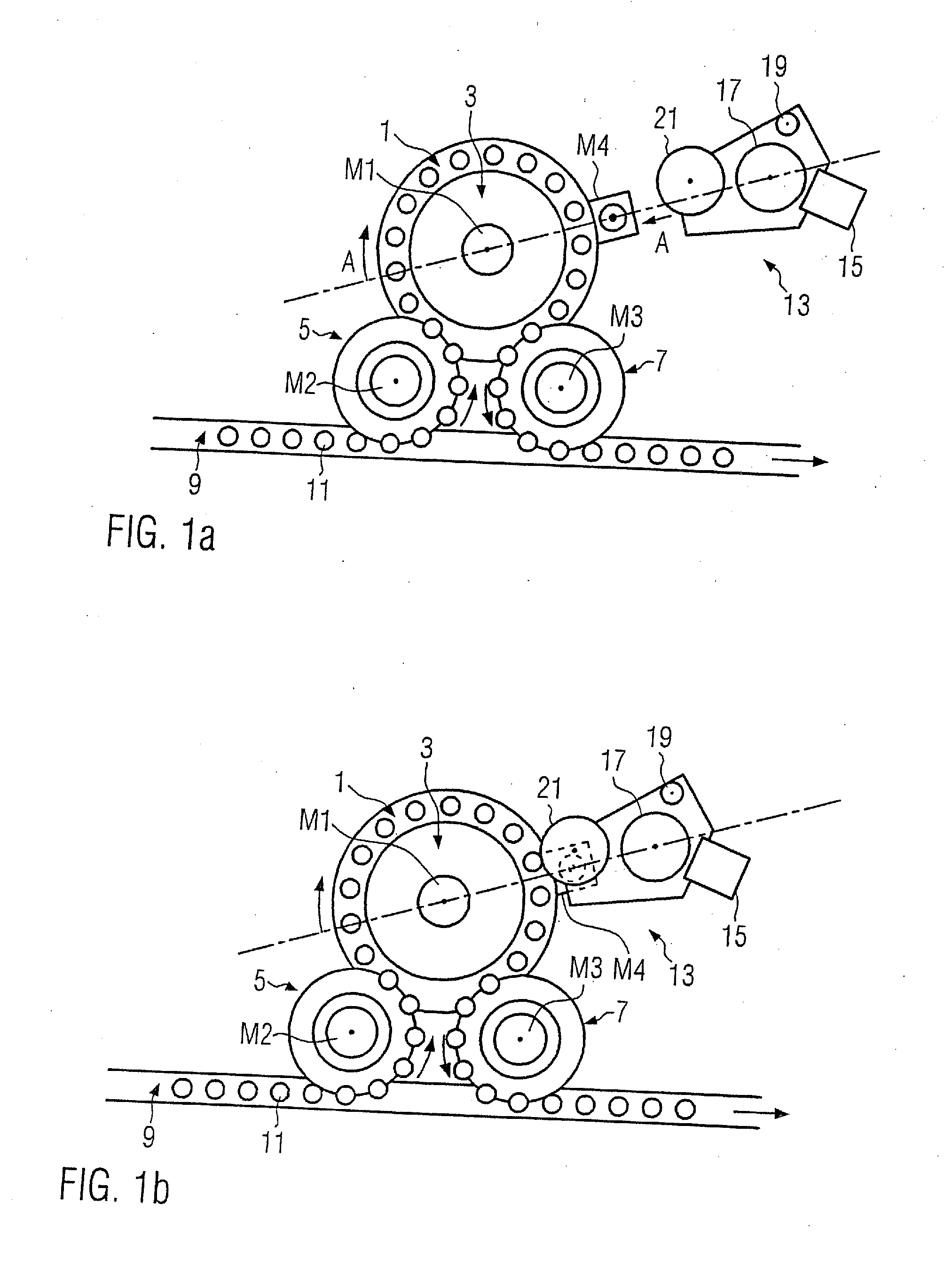
[0008]Thus it is the problem of the present disclosure to prepare a machine for labeling containers in which the exchange or replacement of labeling sets is simplified without losing the advantage of a set's having its own motor.
[0009]This problem is solved by the machine for labeling containers, especially bottles and the like. By the separation of a labeling set into a labeling module and an affiliated motor, whereby the motor of the labeling module remains on the stationary machine rack when there is a change or replacement of the labeling module, it is possible to decrease significantly the size and weight of the part of the labeling set that is changed or replaced, i.e. the labeling module, so that a replacement or change is simplified and, additionally, the store volume is made smaller and the drive engineering expenditure is reduced. At the same time at least one labeling module has its own motor whereby, even in prior art, the use of gear wheels, chains, toothed belts, etc. is reduced. Further, machine costs are decreased since in comparison with prior art, fewer motors in all are used in the case more changeable labeling sets are employed. It is only to be noted that the remaining motor on the stationary machine rack is intended, if necessary, to drive different labeling sets in synchronicity with the other motors.
[0013]Preferably the motor, in particular a servo motor, can have a p.t.o. shaft whereby the labeling module is pivoted on the p.t.o. shaft in a docked state. A projecting p.t.o. shaft facilitates the alignment and docking of the labeling modules. At the same time the p.t.o. shaft allows the spatial separation of the drive function by the motor from the labeling function carried out by the labeling module.

Problems solved by technology

Thus it is the problem of the present disclosure to prepare a machine for labeling containers in which the exchange or replacement of labeling sets is simplified without losing the advantage of a set's having its own motor.
Further, machine costs are decreased since in comparison with prior art, fewer motors in all are used in the case more changeable labeling sets are employed.

Method used


Image

  • Machine for labeling containers
  • Machine for labeling containers
  • Machine for labeling containers

Examples


first embodiment

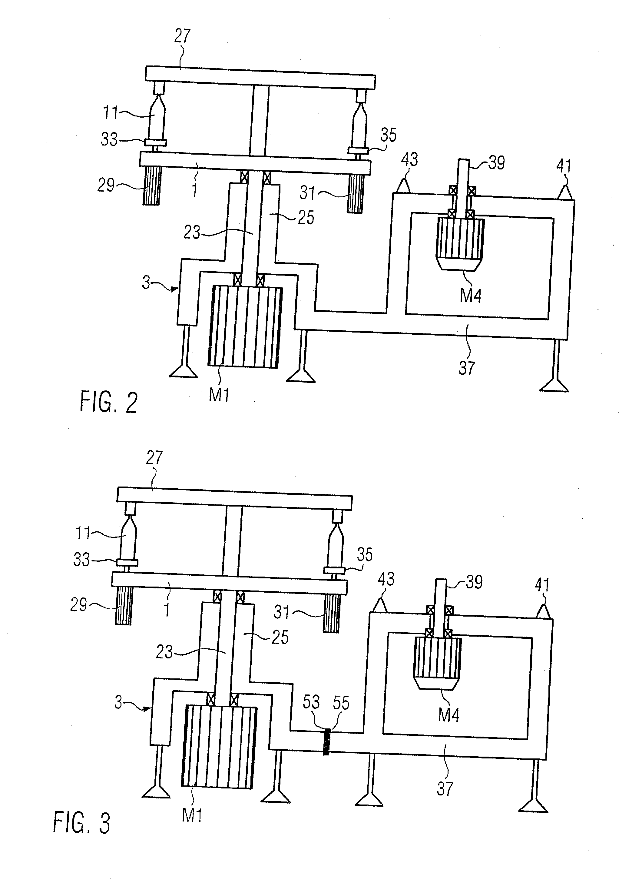
[0033]FIG. 2 shows a schematic cross-sectional representation, along the cut line AA in FIG. 1a, from the side of the labeling machine without the labeling module [13].

[0034]The stationary machine rack [13] with its motor [M1] is recognizable the vertical shaft [23] of which is inserted into a hollow bearing column [25] of the machine rack [3]. The rotary table [1] and a possible top [27] situated over it are driven over the vertical shaft [23]. Additional motors [29, 31] are arranged on the rotary table [1] that serve to drive the rotary plates [33, 35]. The containers [11] to be labeled are carried on these rotary plates [33, 35] and in the labeling process are guided past the gripper cylinder [21] of the labeling module [13]. The motors [29, 31] are driven synchronously with the other motors as to position and speed.

[0035]The stationary machine rack [3] formed in one piece in this embodiment further comprises a carrying rack [37] that carries the motor [M4] serving to drive the ...

third embodiment

[0041]Further in the third embodiment there is a recognition unit [63] on the labeling module [13] that is connected with the control unit [61] as well, in the docked state (FIG. 4b). The stated connections could be plug-in connectors but it is also conceivable to make them wireless, for example by radio or optical.

[0042]The recognition unit [63] transmits identification data to the control unit [61] so that the motor [M4] can be controlled by the control unit [61] corresponding to the demands of the labeling module [13]. If a 20-part rotary table [1] is used and a 5-part labeling module, then the motors [M1 and M4] should drive the rotary table [1] or the gripper cylinder [21] at a speed ratio of 1:4. If the labeling module [13] is then replaced by another labeling module with which an 8-part gripping cylinder [21] is used, the control unit [61] should control the motors [M1 and M4] so that there is a speed ratio of 1:2.5. Thus with the use of different labeling modules [13] there ...


PUM

PropertyMeasurementUnit
Speedaaaaaaaaaa

Abstract

A machine for labeling containers, especially bottles or the like, with a stationary machine rack on which a rotary table for conveying containers is supported, and at least one labeling module, arranged to be interchangeable at or on a machine rack, for labeling the containers being guided past the labeling module by the rotary table wherein its own motor is assigned respectively to the rotary table and at least one labeling module. In order to simplify a change or replacement of a labeling module, the motor is located on the machine rack and remains there.

Description

CROSS-REFERENCE TO RELATED APPLICATION[0001]The present application claims the benefit of priority of German Patent Application No. 10 2006 062 510.2, filed Dec. 29, 2006. The entire text of the priority application is incorporated herein by reference in its entirety.FIELD OF DISCLOSURE[0002]The disclosure concerns a machine for labeling containers, especially bottles or the like, with a stationary machine rack on which a rotary table for conveying containers is supported, and at least one labeling module, arranged to be interchangeable at or on a machine rack, for labeling the containers being guided past the labeling module by the rotary table wherein its own motor is assigned respectively to the rotary table and at least one labeling module.BACKGROUND[0003]Such labeling machines are known from DE19741476, for example. In the labeling machine described there a rotary table is supported upon a table top arranged on a under-rack. On the circumference of the rotary table labeling set...

Claims


Application Information

Patent Timeline
IPC IPC(8): B65C9/42B65C3/12
CPCB65C9/0062Y10T156/1773Y10T156/1771
Inventor MEINZINGER, RUPERT
Owner KRONES AG
Learn More