
Bathtub waste and overflow assembly

a bath tub and waste technology, applied in the field of bath tub waste and overflow assemblies, can solve the problems of many trial and error attempts to get the piping length, inefficiency and increased costs, and installation problems of installers,

Inactive Publication Date: 2008-07-03
BURR ERIC
View PDF17 Cites 25 Cited by
  • Summary
  • Abstract
  • Description
  • Claims
  • Application Information

AI Technical Summary

Benefits of technology

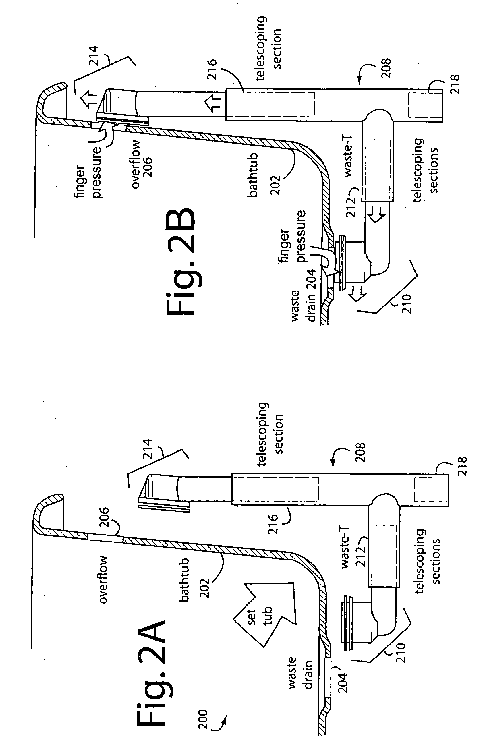
[0006]An advantage of the present invention is a bathtub waste and overflow drain assembly is provided that allows final adjustments of the drain and overflow extensions from inside the tub after the tub is put in place. In preferred embodiments, no tightening or cinching is required. Cinching refers to any sealing methods that inhibit motion of the telescoping pipes to the point that adjustment can no longer be readily made in accord with the invention herein.
[0007]The above summary of the present invention is not intended to represent each disclosed embodiment, or every aspect, of the present invention. Other aspects and example embodiments are provided in the figures and the detailed description that follow.

Problems solved by technology

Bathtub waste and overflow assemblies can very often present unique problems to their installers since there is no easy way to access the waste and overflow and related pipe fittings after the tub is set in place and the walls or flooring are sealed.
Both solutions lead to inefficiencies and increased costs.
The trouble with conventional fittings and methods is many trial and error attempts are needed to get the piping lengths just right on the waste and overflow.
Often access for tools is limited because fittings can be located above the flooring but below the tub with only a small access hole from below.
Using trial-and-error adjustment methods to get the slip-joints aligned and tightened correctly in a tub wastewater connection are not very practical.
The alternative of leaving the slip-joints not fully tightened is also not very desirable because loose joints can leak.

Method used


Image

  • Bathtub waste and overflow assembly
  • Bathtub waste and overflow assembly
  • Bathtub waste and overflow assembly

Examples


Embodiment Construction

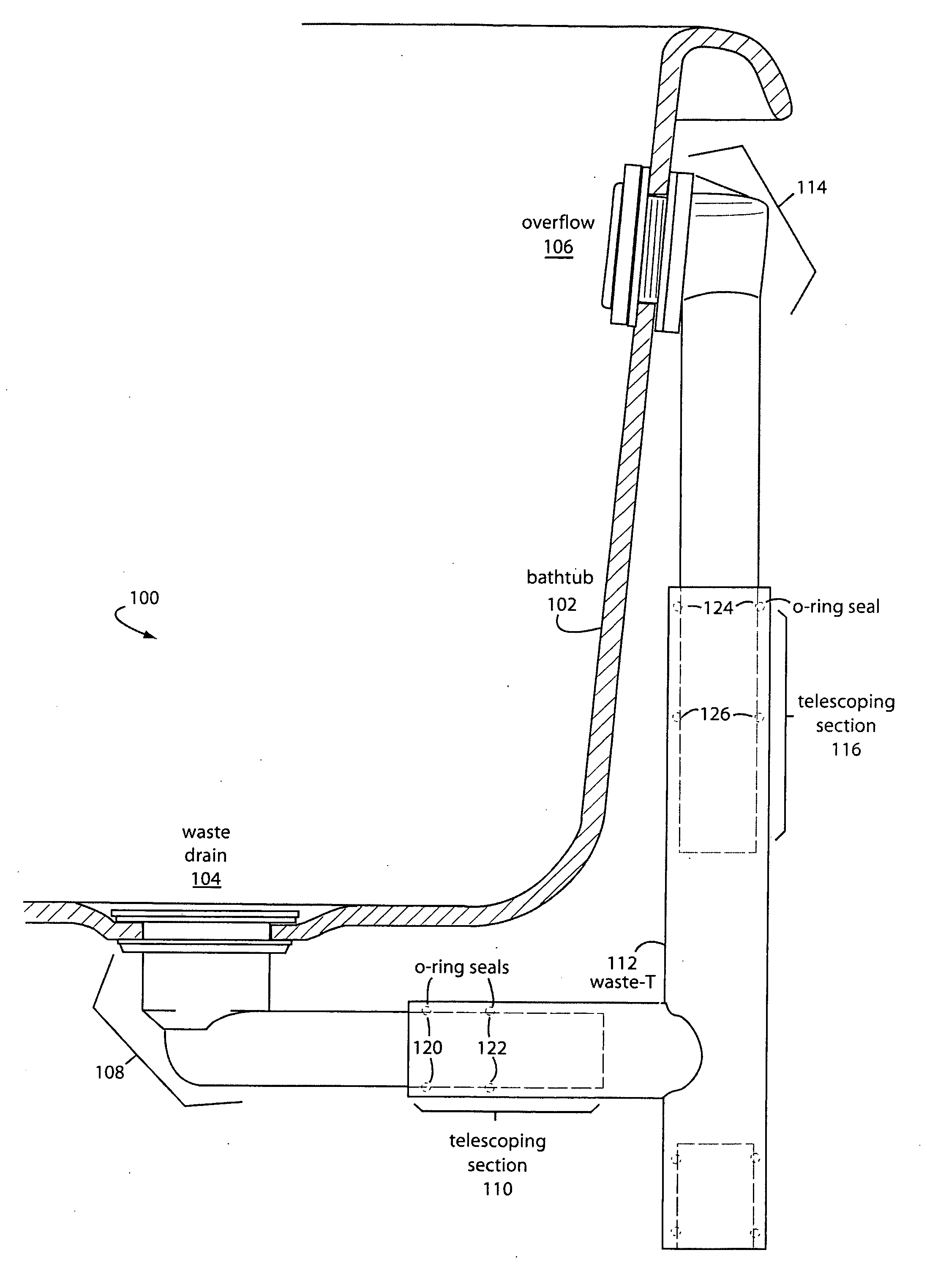
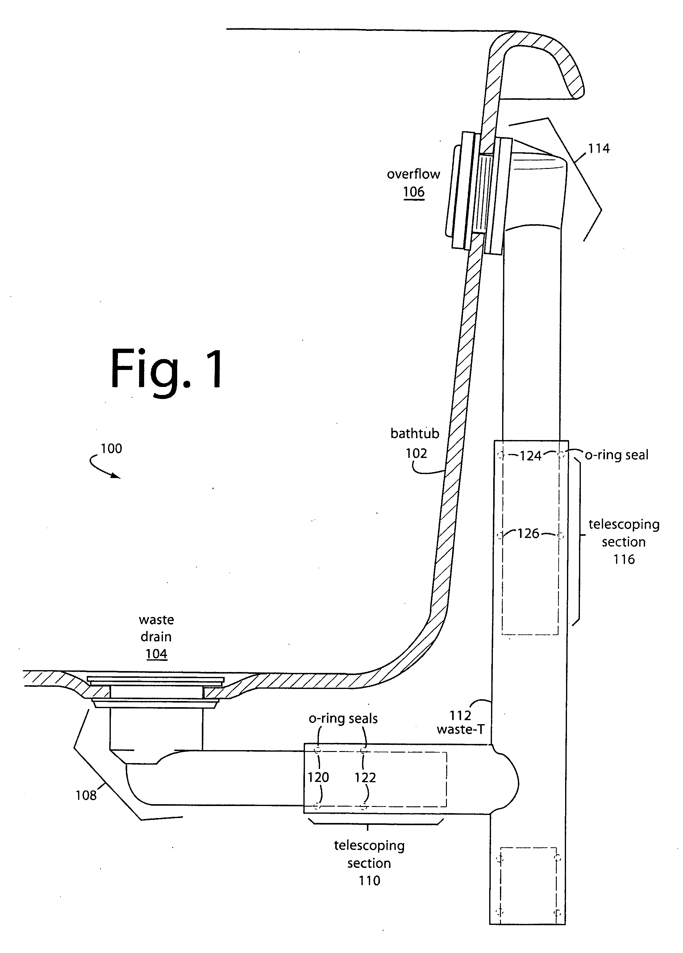
[0012]FIG. 1 represents a bathtub waste and overflow drain assembly embodiment of the present invention, and is referred to herein by the general reference numeral 100. A typical bathtub 102 has a waste drain 104 and an overflow port 106. A waste assembly 108 can slip in-and-out and twist inside a first telescoping section 110 of a waste T-fitting 112. Similarly, an overflow assembly 114 can slip in-and-out and twist inside a second telescoping section 116 of waste T-fitting 112.

[0013]Both the waste assembly 108 and overflow assembly 114 require no nuts, clamps, or collars to be tightened in order to maintain water-tight seals within respective telescoping sections 110 and 116. Instead, any number of different acceptable methods can be employed to seal the joint connections. For example, FIG. 1 shows two sets of O-ring seals, 120 and 122, and 124 and 126. In alternate embodiments just one O-ring may be used, and in other embodiments stops may be provided to prevent the telescoping p...


PUM


Abstract

A bathtub waste and overflow drain assembly comprises a fitting-T with at least two telescoping joints that do not require tightening to stop leaks. Telescoping sections are provided in a T-fitting that allow joint type connections with the drain and overflow assemblies. The drain and overflow fittings need only be roughly placed before or after the tub is set down. The joints allow the installer to pull the fittings below into place through the drain and overflow holes in the tub. The finish covers, gaskets, putty, and drain basket can then be installed from above to complete the job.

Description

FIELD OF THE INVENTION[0001]The present invention relates to plumbing methods and components, and in particular to waste and overflow plumbing for bath tubs.BACKGROUND[0002]Bathtub waste and overflow assemblies can very often present unique problems to their installers since there is no easy way to access the waste and overflow and related pipe fittings after the tub is set in place and the walls or flooring are sealed. In these situations two approaches are possible. Two installers can work together, with one below the tub to support and adjust the waste and overflow and one above to secure the waste and overflow to the tub; or a single installer can make numerous trips above and below the tub to precisely align and secure the fittings. Both solutions lead to inefficiencies and increased costs. The trouble with conventional fittings and methods is many trial and error attempts are needed to get the piping lengths just right on the waste and overflow. Various kits are sold with comp...

Claims


Application Information

Patent Timeline
IPC IPC(8): E03C1/232
CPCE03C1/232
Inventor BURR, ERIC
Owner BURR ERIC
Learn More