
Joint type manipulator

A mechanical finger and joint-type technology, which is applied in the direction of manipulators, program-controlled manipulators, manufacturing tools, etc., can solve the problems of difficult grasping of manipulators and reduce the versatility of manipulators, and achieve the effects of compact structure, quick adjustment and convenient installation

Active Publication Date: 2012-08-22
SUZHOU WEIZHONG TECH DEV CO LTD
View PDF8 Cites 18 Cited by
  • Summary
  • Abstract
  • Description
  • Claims
  • Application Information

AI Technical Summary

Problems solved by technology

[0003] like Figure 10 The shown patent number is 200810030084.8, and the device disclosed in the Chinese patent titled "A Fully Automatic Multifunctional Mechanical Arm" includes a chamfering group 91, a chamfering group fixing block 92, a cylinder 93, and a cylinder connecting block 94 , the jig profile 95, the jig fixing block 96, the L-shaped connecting block 99, and the suction cup 97 and the holding tool 98 fixedly connected to the jig profile 95 and the jig fixing block 96, the chamfering group 91 can be relative to the jig Profile 95 rotates 90-180 degrees to achieve multi-angle grabbing of products. However, such a manipulator still cannot flexibly twist or bend freely according to the shape characteristics of the product to be grabbed, especially for irregular shapes. For products such as products with irregular arc surfaces or other types of products, it is difficult for this kind of manipulator to effectively grab
[0004] On the other hand, in the prior art, the manipulators used to grab or suck the products to be grabbed are generally specially designed according to the shape, material and weight of the products to be grabbed, which are not suitable for other types of products gripping, thus reducing the versatility of the manipulator

Method used


Image

  • Joint type manipulator
  • Joint type manipulator
  • Joint type manipulator

Examples


Embodiment Construction

[0049] The technical solutions of the embodiments of the present invention will be clearly and completely described below in conjunction with the accompanying drawings of the present invention.

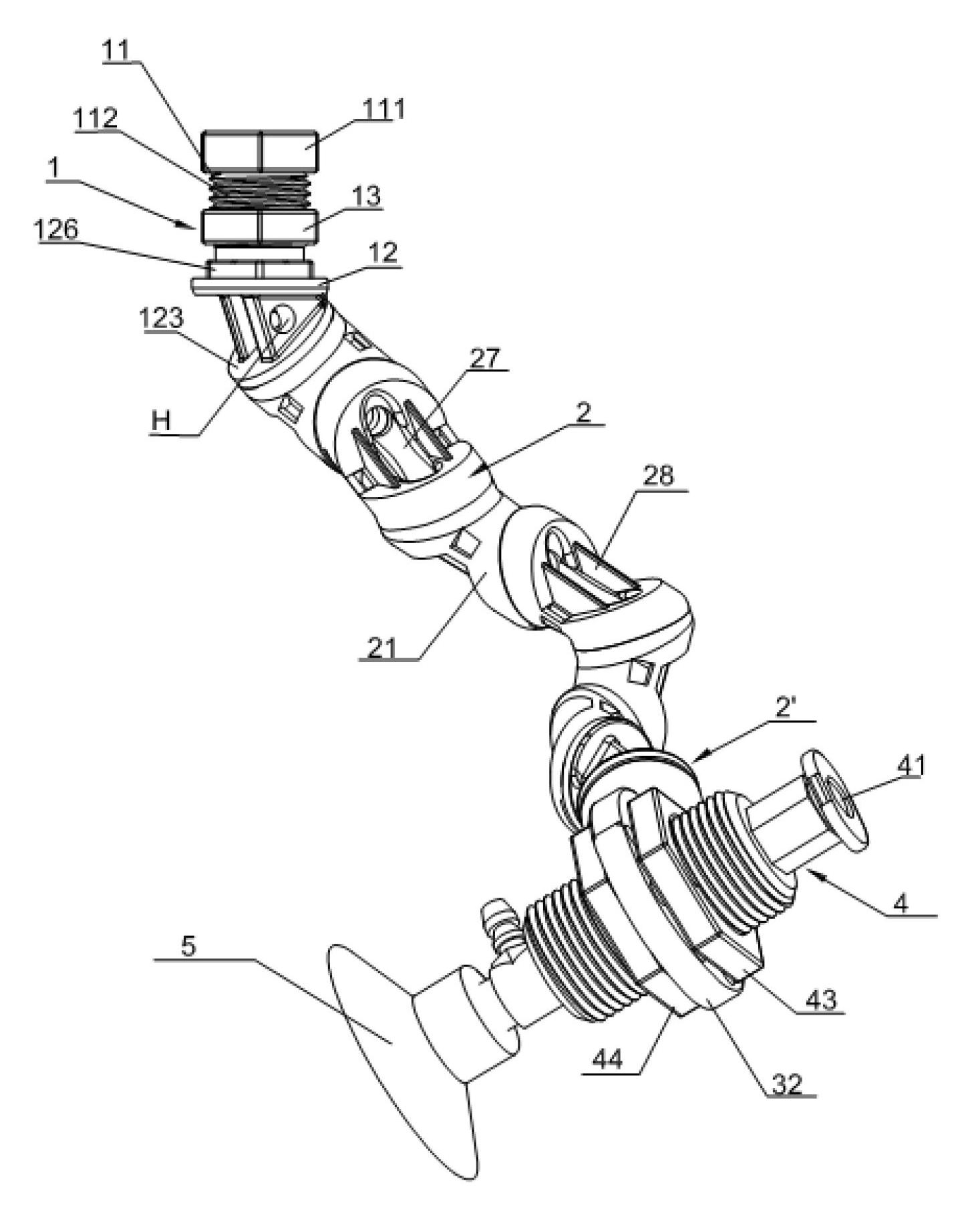
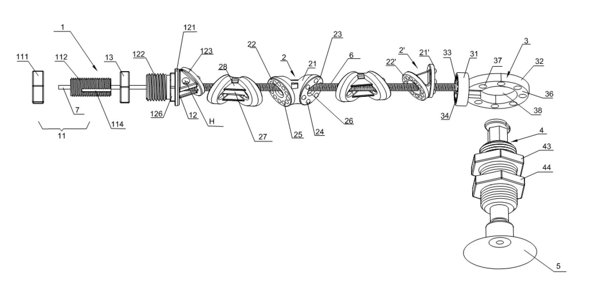
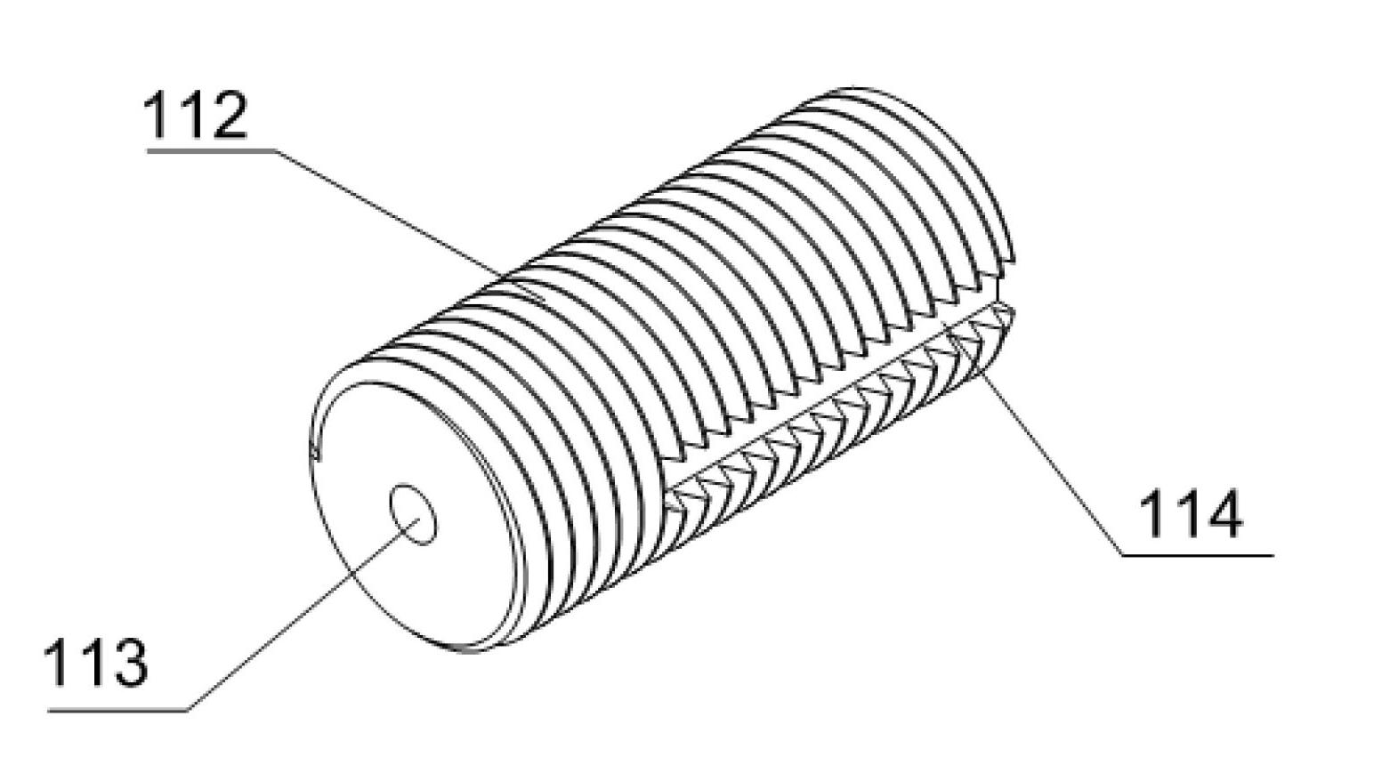
[0050] combine figure 1 , figure 2 Shown, the articulated mechanical finger disclosed in the preferred embodiment of the present invention includes tensioning and fixing components 1 connected in sequence, a plurality of connecting parts 2, a fixing bracket 3, and a cylinder 4 connected with the fixing bracket, and the cylinder There is a suction cup 5 at the end of the handle, the tightening and fixing component 1, the connecting piece 2, and the fixing bracket 3 are connected by the spring 6 and the steel wire 7 in the spring 6, and the articulated mechanical finger is fixedly connected by the tightening and fixing component 1 On the manipulator fixed plate 8.

[0051] combine image 3 , Figure 4A , 4B As shown, the tensioning and fixing assembly 1 includes a tensioning memb...


PUM


Abstract

The invention discloses a joint type manipulator. The joint type mechanical manipulator comprises a tensioning fixed component, a plurality of connecting pieces and a fixed support which are sequentially connected with one another through springs and steel wires, wherein the tensioning fixed component comprises a tensioning part and a fixed part which are connected with each other, the tensioning and releasing of the steel wires among the tensioning fixed component, the connecting pieces and the fixed support are adjusted by adjusting the relative position of the tensioning part and the fixed part, each connecting piece comprises a first end surface, a second end surface, and a middle part for connecting the first end surface with the second end surface, a plurality of projections and grooves which are matched with each other in an embedded way, an through holes through which the springs can pass are respectively formed on the first end surface and the second end surface, the fixed support is provided with a first support connected with the connecting pieces, and other ends of the springs and the steel wires are fixed on the first support. The extension position and length of the manipulator can be freely adjusted, and the flexibility and universality of the manipulator are improved.

Description

technical field [0001] The invention relates to a mechanical finger, in particular to a multifunctional joint-type mechanical finger capable of freely twisting and extending at multiple angles. Background technique [0002] In recent years, with the advancement of science and technology and the continuous expansion of automated production scale, manipulators have been widely used in many fields such as home appliance production, automobile manufacturing, medical and health, and military. The actions such as grasping of the product are completed, but the angle of adjustment of the manipulator in the prior art can generally only be adjusted in three directions of X, Y, and Z. [0003] Such as Figure 10 The shown patent number is 200810030084.8, and the device disclosed in the Chinese patent titled "A Fully Automatic Multifunctional Mechanical Arm" includes a chamfering group 91, a chamfering group fixing block 92, a cylinder 93, and a cylinder connecting block 94 , the jig p...

Claims


Application Information

Patent Timeline
IPC IPC(8): B25J9/08B25J9/02B25J9/06
Inventor 滑英宾
Owner SUZHOU WEIZHONG TECH DEV CO LTD
Learn More