
Heat protection systems and methods for remote viewing devices

a technology of remote viewing and heat protection system, applied in the field of remote viewing devices, can solve problems such as temperature-related problems, failures, and failures, and achieve the effects of preventing the temperature from rising

Active Publication Date: 2008-06-26
GE INSPECTION TECH LP
View PDF76 Cites 24 Cited by
  • Summary
  • Abstract
  • Description
  • Claims
  • Application Information

AI Technical Summary

Benefits of technology

[0009]These and other needs are met by an exemplary a remote viewing device comprising an insertion tube, at least one light source (e.g., one or more light emitting diodes) that is disposed within the insertion tube, an imager that is disposed within the insertion tube, and at least one heat protection element (e.g., one or more of a heat pipe, a heat relocation element and a thermal isolation element) that is disposed at a predetermined location (e.g., at least partially between the at least one light source and the image) within the insertion tube and that is effective to lower the temperature of at least one of the imager and the at least one light source.
[0010]Another exemplary remote viewing device comprises an insertion tube, at least one light source that is disposed within the insertion tube, an imager that is disposed proximate the at least one light source, wherein the imager has a predetermined upper temperature threshold, and at least one heat protection element that is disposed at a predetermined location within the insertion tube such that the at least one light source is operable at a temperature equal to at least the predetermined upper temperature threshold of the imager without causing temperature-related damage to the imager.
[0011]Yet another exemplary remote viewing device comprises an insertion tube, at least one light source that is disposed within the insertion tube, wherein each of the at least one light source has a predetermined upper temperature threshold, an imager that is disposed proximate the at least one light source, wherein the imager has a predetermined upper temperature threshold, and at least one heat protection element that is disposed at a predetermined location within the insertion tube such that the remote viewing device is operable in an environment having a temperature greater than at least one of the predetermined upper temperature threshold of the at least one light source and the predetermined upper temperature threshold of the imager without causing temperature-related damage to either of the at least one light source and the imager.

Problems solved by technology

Certain parts of a remote viewing device are heat sensitive, such that they cease to function either entirely or at a satisfactory level if exposed to temperatures above a certain threshold.
For example, light emitting diodes, which often act as the one or more light sources for a remote viewing device, can start to degrade and fail at temperatures above 120° C. Moreover, portions of the viewing head (e.g., the imager) of a remote viewing device likewise can begin to perform suboptimally at temperatures at or near 80° C., and can be vulnerable to failure at temperatures as low as about 10° C.
This can be problematic when, as is often the case, the one or more light sources are positioned near the imager of the remote viewing device.
However, doing so also will cause the light source(s) to radiate heat, which can be at or above 100° when reaching the nearby imager.
Another temperature-related problem can occur due to the usage environment of the remote viewing device.
This also creates a Catch-22 whereby one is forced either to wait to perform such inspections until the engine or equipment has definitely cooled below a temperature that could potentially harm the light source and / or the imager, thus disadvantageously requiring the aircraft or equipment to be non-operational during the waiting period, or, instead, to perform an inspection on a hot engine or piece of equipment, thus risking temperature-related harm to the light source and / or to the imager of the borescope.

Method used


Image

  • Heat protection systems and methods for remote viewing devices
  • Heat protection systems and methods for remote viewing devices
  • Heat protection systems and methods for remote viewing devices

Examples


Embodiment Construction

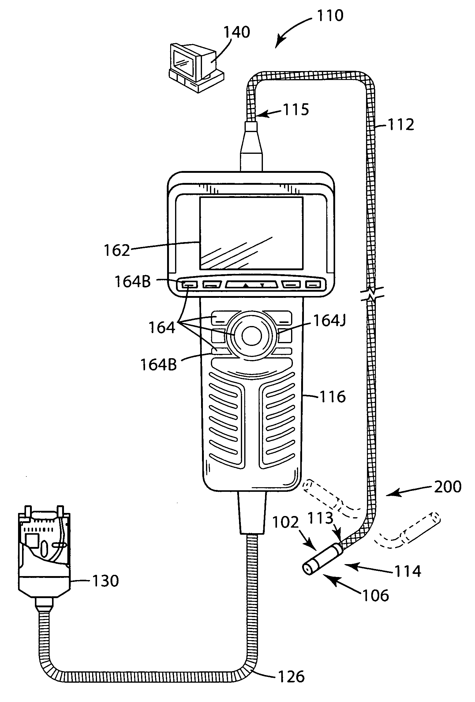
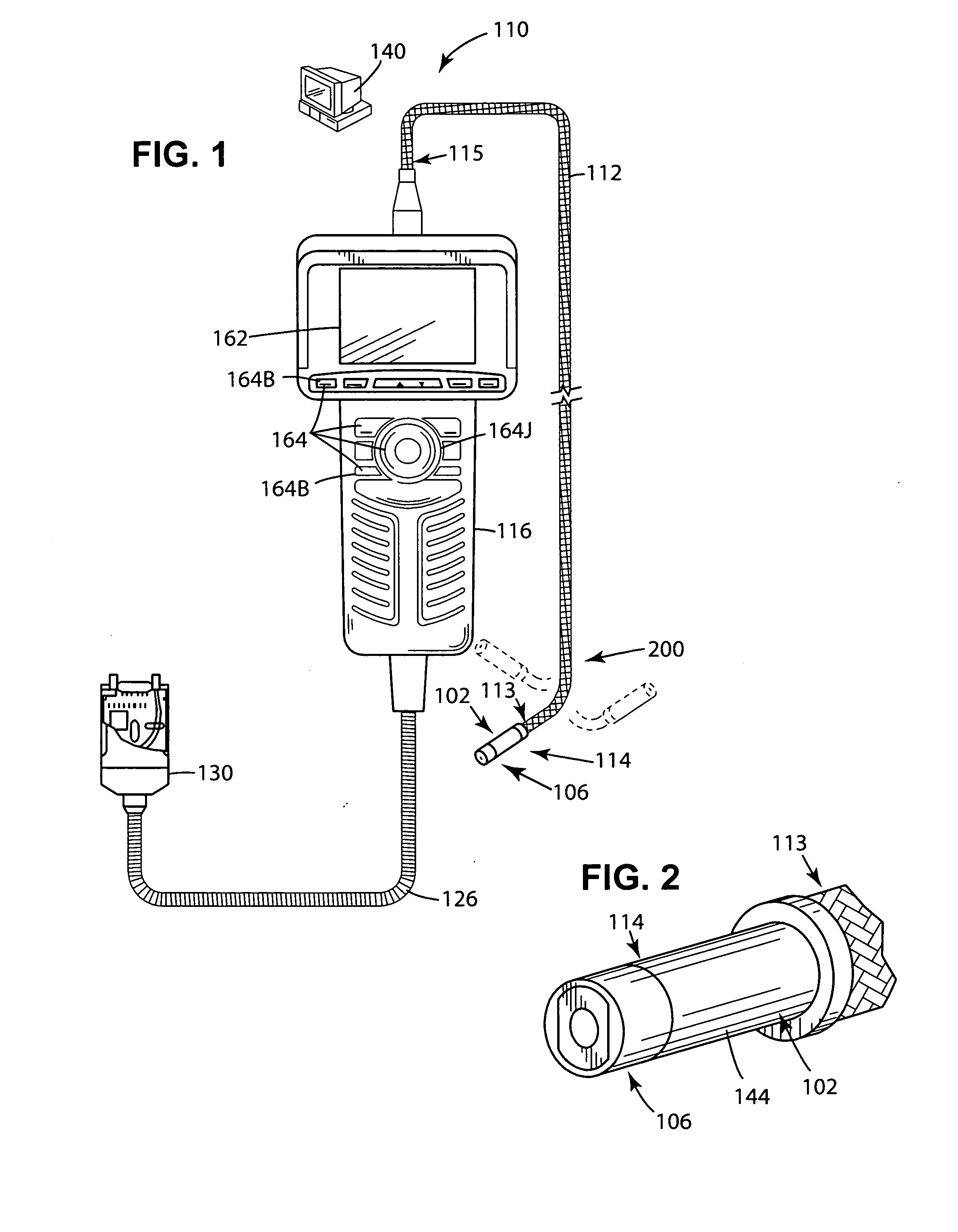
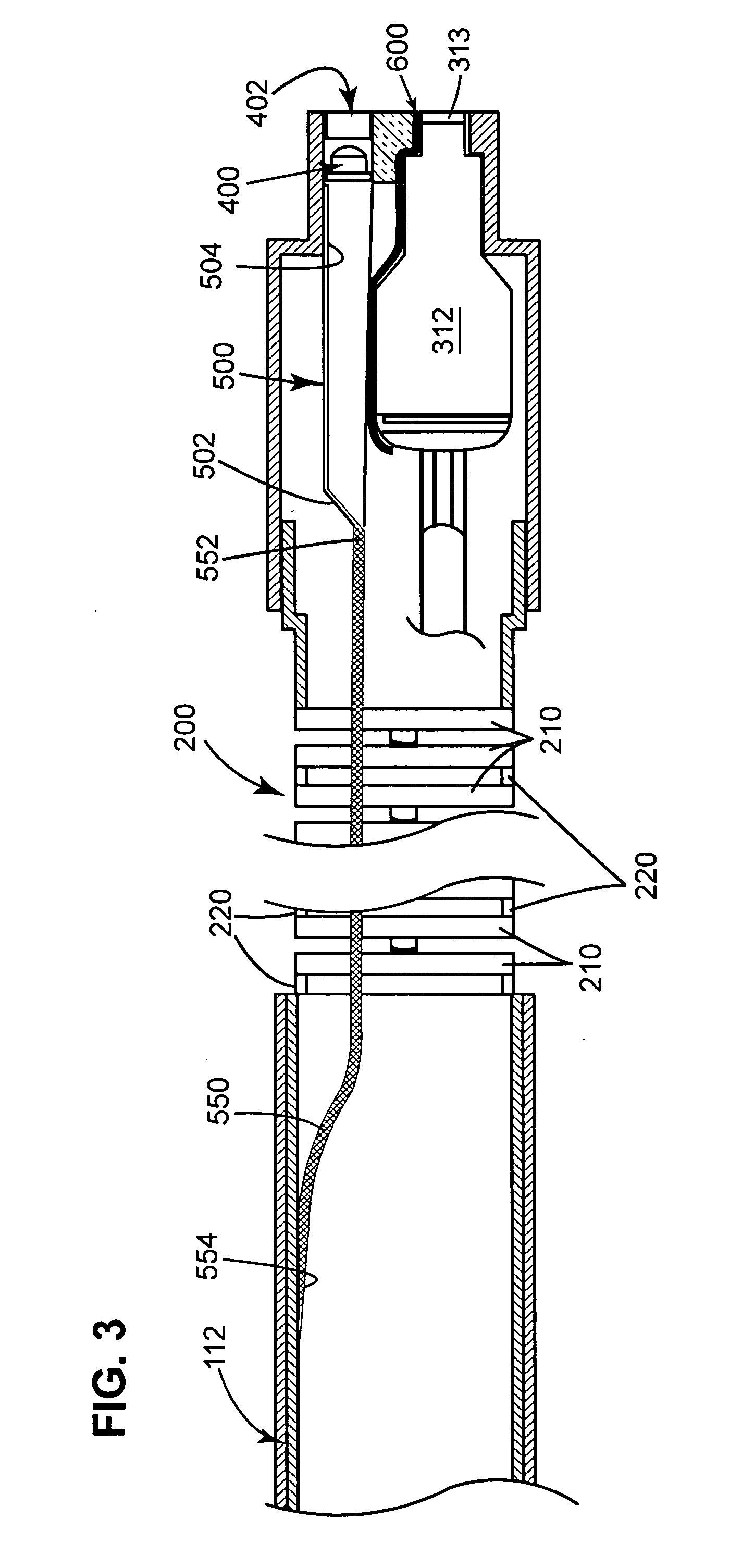
[0018]FIGS. 1-3 illustrate an exemplary embodiment of a remote viewing device 110 that includes a detachable optical tip 106 and a viewing head 102, each of which comprises a portion of a viewing head assembly 114. As best illustrated in FIGS. 2 and 3, the viewing head assembly 114 also includes a metal canister (can) 144 that surrounds an imager 312 and one or more associated lenses 313, which direct and focus incoming light towards the imager.

[0019]The remote viewing device 110 also includes various additional components, such as a power plug 130, an umbilical cord 126, a hand piece 116, and an insertion tube 112, each generally arranged as depicted in FIG. 1. The insertion tube 112 includes at least one articulation section 200 (see FIGS. 1 and 3) that is located comparatively closer to its distal end 113 than its proximal end 115.

[0020]The presence of the articulation section 200 enables an operator or other user of the remote viewing device 110 to control movement (e.g., bendin...


PUM


Abstract

Heat isolation and relocation systems and methods are provided to enable utilization of a remote viewing device in a wider range of temperature environments and while operating its one or more light sources at or near full power without fear of causing temperature-related harm to the one or more light sources and / or to the imager, even if the imager is positioned nearby the one or more light sources.

Description

FIELD OF THE INVENTION[0001]This invention relates generally to remote viewing devices, and, in particular, to systems and methods for protecting one or more temperature-sensitive components (e.g., one or more light sources, an imager) of a remote viewing device by isolating and / or relocating heat away from such components.BACKGROUND OF THE INVENTION[0002]A remote viewing device, such as an endoscope or a borescope, often is characterized as having an elongated and flexible insertion tube or probe with a viewing head assembly at its forward (i.e., distal) end, and a control section at its rear (i.e., proximal) end. Typically, the insertion tube is about 5 to 100 feet in length and approximately one-sixth to one-half inch in diameter, but it can have dimensions outside of these ranges as well. The viewing head assembly includes an optical tip and an imager, wherein at least one lens is spaced apart from, but is positioned relative to (e.g., axially aligned with) the imager. One or mo...

Claims


Application Information

Patent Timeline
IPC IPC(8): H04N7/18
CPCA61B1/05A61B1/0676A61B1/0684G02B23/2476H04N7/183A61B1/12A61B1/128
Inventor SCOTT, JOSHUA L.KARPEN, THOMAS W.
Owner GE INSPECTION TECH LP
Learn More