
Stereoscopic endoscope

a technology of endoscope and stereoscopic image, which is applied in the field of stereoscopic imaging systems, can solve the problems of inability to always correct mismatches in other parameters, affecting both images, and affecting image rotation,

Active Publication Date: 2008-06-26
INTUITIVE SURGICAL OPERATIONS INC
View PDF45 Cites 203 Cited by
  • Summary
  • Abstract
  • Description
  • Claims
  • Application Information

AI Technical Summary

Problems solved by technology

In addition, except for the image location, mismatches in the other parameters are difficult to correct for in image post-processing without introducing imaging artifacts.
Errors in two of the translation axes between the sensors affect the relative horizontal and vertical positions of the viewed images, while errors in the third translation axis, the axis perpendicular to the sensor surface, affects both the image scale (if the objective is not telecentric in image space) and focus.
Errors in rotation between the two image sensors, around the axis perpendicular to the sensor surface, directly affect image rotation and cannot always be corrected by alignment of the optics, while rotation errors about the other two axes affect the focal plane shifts across the imaging field.

Method used


Image

  • Stereoscopic endoscope
  • Stereoscopic endoscope
  • Stereoscopic endoscope

Examples


Embodiment Construction

[0025]In the following description, reference is made to the accompanying drawings, which illustrate embodiments of the invention. It is understood that other embodiments may be used, and mechanical, compositional, structural, electrical, and operational changes may be made, without departing from the spirit and scope of this disclosure. The following detailed description is not to be taken in a limiting sense. The scope of the embodiments of the invention is defined only by the claims of the issued patent.

[0026]The terminology used in this description is to describe particular embodiments only and is not intended to limit the invention. Spatially relative terms, such as “beneath”, “below”, “lower”, “above”, “upper”, “underlying”, “outside”, “between”, and the like may be used to describe one element's or feature's relationship to another as illustrated in the figures. The spatially relative terms are for ease of description and are intended to encompass different orientations of th...


PUM


Abstract

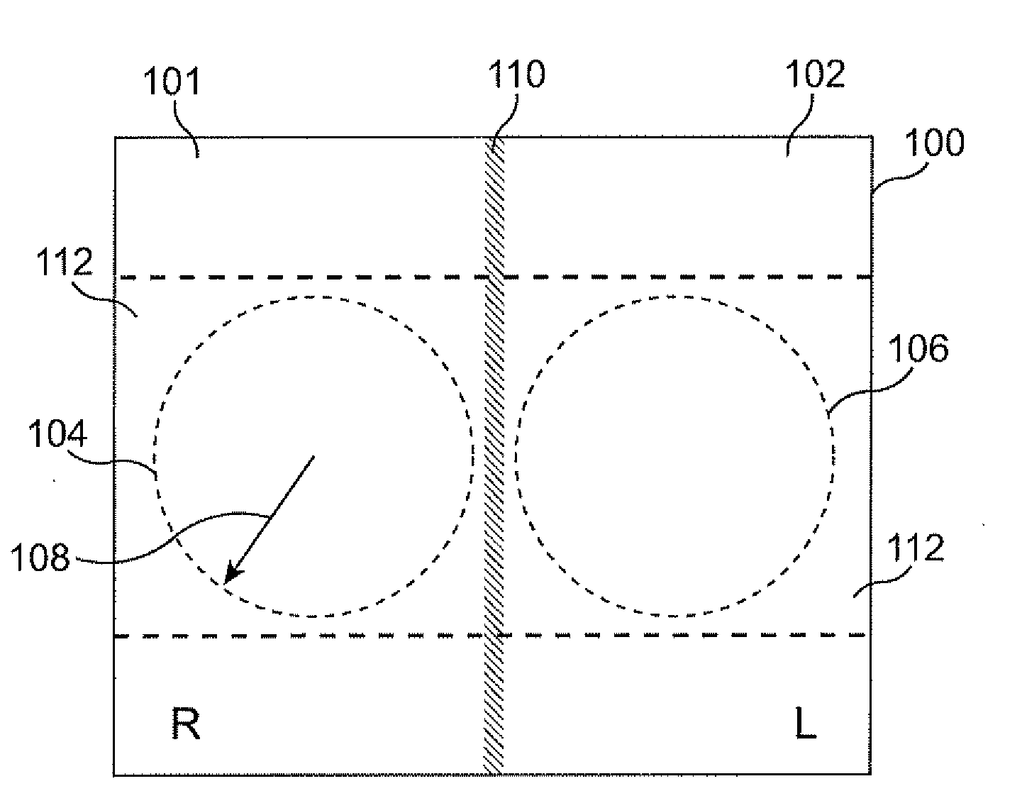
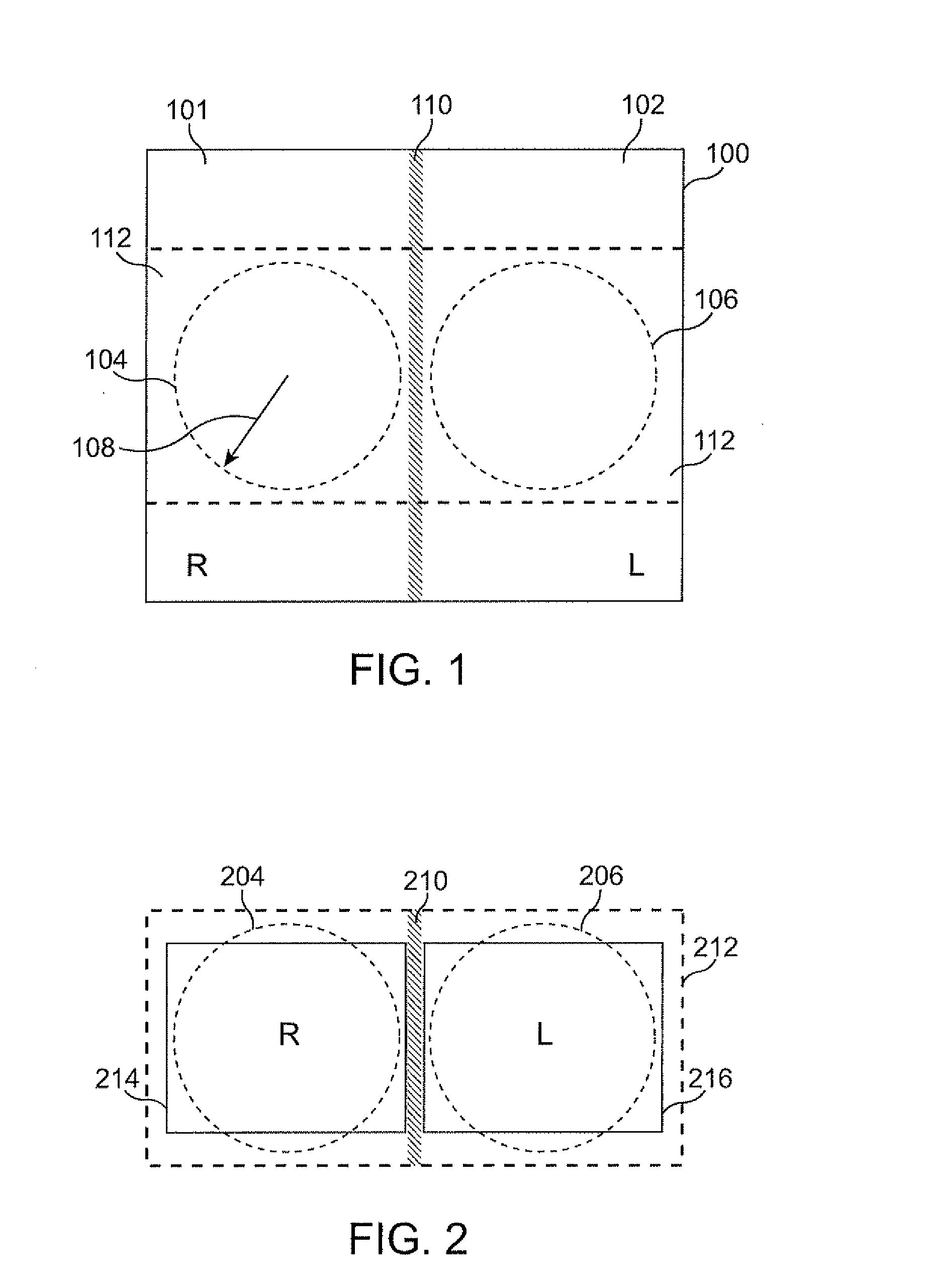
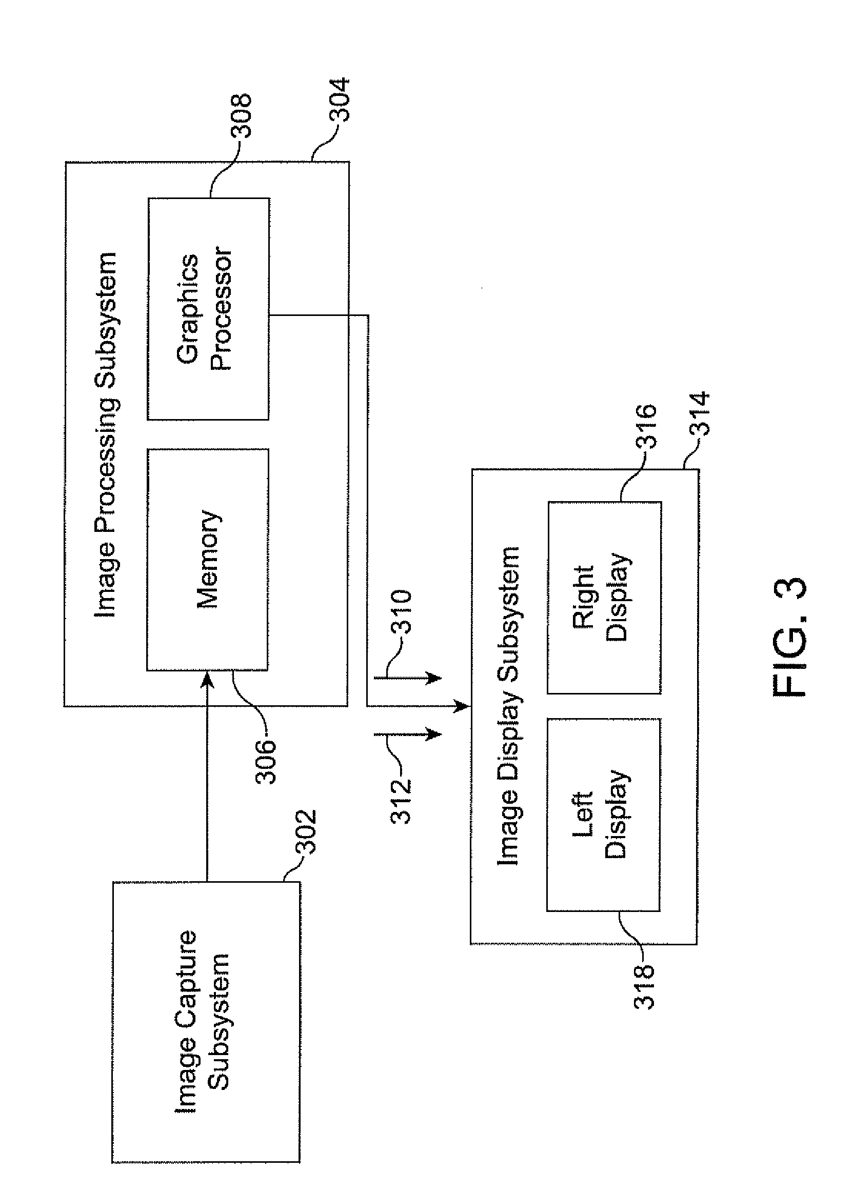
Two side-by-side optical paths transmit stereoscopic right side and left side images onto the surface of a single image sensing chip. The single image sensing chip may be placed at various orientations with respect to the lens trains in the optical paths. In some embodiments a single prism is used to turn the light for both the right side and left side images onto the single image sensing chip. In other embodiments one prism is used to turn the light for the right side image and another prism is used to turn the light for the left side image, and the reflective surfaces of the two prisms are substantially coplanar such that the right side and left side images are incident on the single image sensor chip.

Description

CROSS REFERENCE TO RELATED APPLICATIONS[0001]Not applicable.BACKGROUND[0002]1. Field of Invention[0003]The invention pertains to stereoscopic imaging systems, and more particularly to stereoscopic image capture endoscopes.[0004]2. Background Art[0005]The field of minimally invasive surgery (e.g., laparoscopic surgery) requires increasingly smaller, increasingly mobile stereoscopic imaging systems. Stereoscopic endoscopes are typically mounted at the distal end of rigid shafts that extend through a cannula so as to image a surgical site during, e.g., robot-assisted surgery.[0006]To get acceptable stereoscopic imaging without causing viewer fatigue or eyestrain, the images of the target object viewed by the two imaging systems should match in at least the following alignment parameters: (1) image location along the horizontal axis; (2) image location along the vertical axis; (3) image rotation; (4) image scale; (5) geometric distortion; (5) focus at the image center; (6) focal shift a...

Claims


Application Information

Patent Timeline
IPC IPC(8): H04N13/00
CPCA61B1/00193G02B23/2415A61B1/00009A61B1/00045G02B27/22A61B1/00096A61B1/00163A61B1/05G02B5/045A61B1/04A61B1/051A61B1/00194A61B1/044A61B1/000095
Inventor SHAFER, DAVID CHRISTOPHERLEINER, DENNIS C.
Owner INTUITIVE SURGICAL OPERATIONS INC
Learn More