Methods of Enhancing Power Amplifier Linearity

a technology of linearity and power amplifier, applied in the direction of amplifier, lookup table adaptive predistortion, transmission, etc., can solve the problems of high peak-to-mean power ratio of modulated signals, high linearity of rf input signals, and high power consumption of modulated signals, so as to improve the performance of a transmitter system, low cost, and low power consumption

Inactive Publication Date: 2008-06-19
SIGE SEMICON
View PDF20 Cites 13 Cited by
  • Summary
  • Abstract
  • Description
  • Claims
  • Application Information

AI Technical Summary

Benefits of technology

[0008]The objective of the present invention is to improve the performance of a transmitter system that utilizes a conventional PA of moderate linearity so that it meets modulation requirements in accordance with predetermined modulation schemes and with low cost and low power consumption.

Problems solved by technology

These modulated signals tend to have high peak-to-mean power ratios and require highly linear amplification.
The disadvantage of the architecture and method disclosed in U.S. Pat. No. 6,275,685 B1 is that analog predistortion is applied to an RF input signal.
It is a disadvantage that the complexity of the power amplifier is high, the die size and the costs are also significant.
It is well understood to those skilled in the art of PA design that operating a RF power amplifier at a power much lower than its maximum capability reduces the efficiency of conversion of DC power to RF power.
Moreover, the linearity back-off becomes a larger disadvantage, due to a larger efficiency impact, as the RF power requirement increases.
In addition, it becomes more difficult to realize such a PA with the required performance using low cost technology.

Method used


Image

  • Methods of Enhancing Power Amplifier Linearity
  • Methods of Enhancing Power Amplifier Linearity
  • Methods of Enhancing Power Amplifier Linearity

Examples


Embodiment Construction

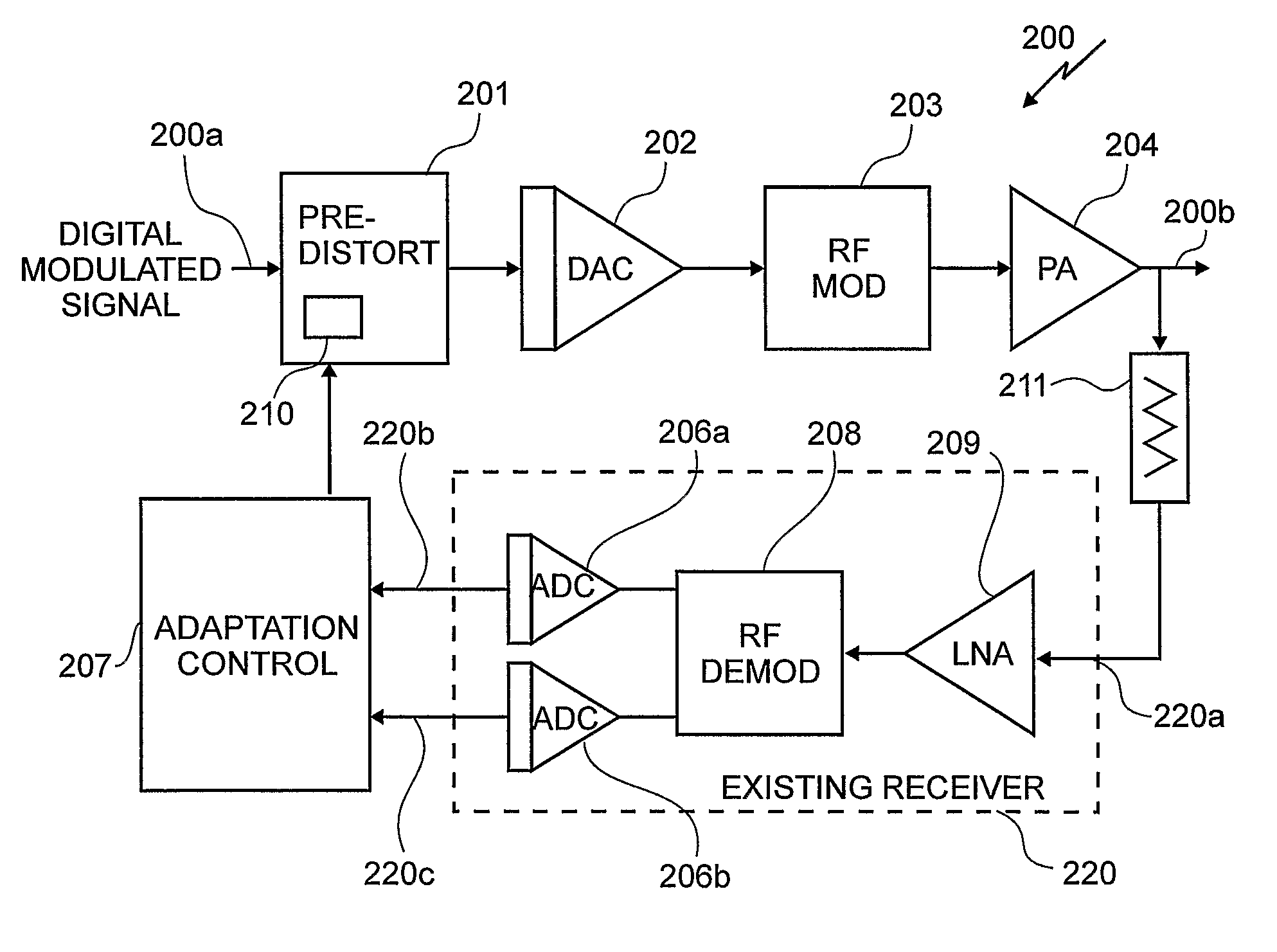
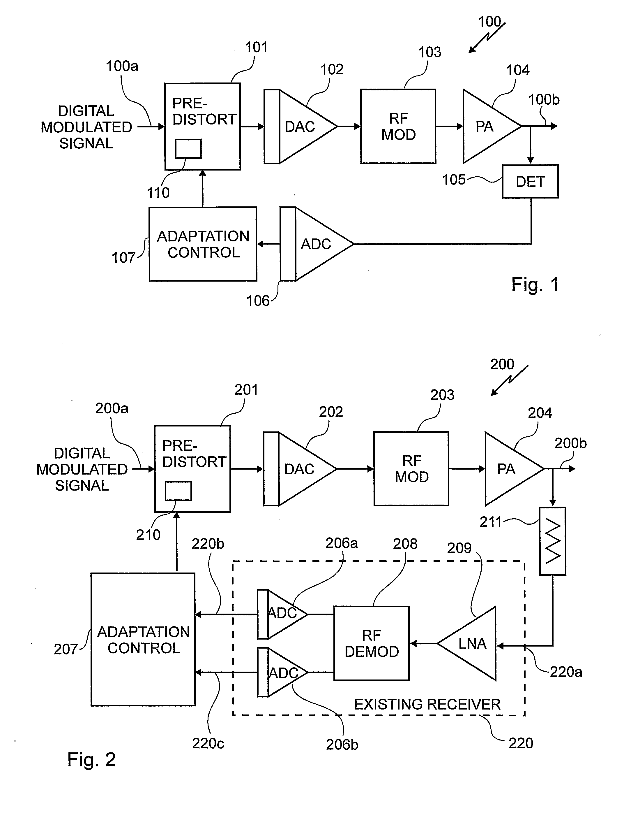
[0014]FIG. 1 illustrates a portion of a transmitter system 100 having an input port 100a for receiving a digital modulated signal and having an output port 100b for providing a radio frequency (RF) signal therefrom. A digital predistorter circuit 101 has an input port coupled to port 100a for receiving the digital modulated signal and for providing a predistorted digital modulated signal from an output port thereof. Disposed within the digital predistorter circuit 101 is a lookup table (LUT) 110 for storing of predistortion data. Coupled to an output port of the digital predistorter circuit 101 is a digital to analog converter (DAC) 102 for converting the predistorted digital modulated signal to an analog representation thereof. A RF modulator 103 receives this analog representation and modulates this signal to form a modulated signal that is provided to an input port of a power amplifier (PA) 104 circuit. The PA 104 amplifies the modulated signal and provides it to the output port ...


PUM


Abstract

A novel method of enhancing power amplifier linearity is disclosed. The invention is for use within a transceiver system and provides a method in the digital domain for predistorting a digital modulated signal to compensate for the non-linearity properties of the power amplifier and other components within the transmitter system. The RF output signal of the transmitter circuit is sampled and the corresponding amplitude and phase are detected using a receiver circuit. In dependence upon the amplitude and phase information, a look-up table is indexed to select the predistortion data and predistortion of the digital modulated signal occurs within the predistortion circuit.

Description

FIELD OF THE INVENTION[0001]The invention relates to the field of RF transmitter circuits and more specifically to the field of RF transmitter circuits that employ a predistorter circuit.BACKGROUND OF THE INVENTION[0002]Modern digital wireless communication systems use complex modulation schemes in order to provide data between a transmitter and a receiver at high data rates using a modulated wireless signal within a limited spectral bandwidth.[0003]These modulated signals tend to have high peak-to-mean power ratios and require highly linear amplification. One example of such modulation is the OFDM that is used in a wireless LAN standard 802.11g, as is well known to those of skill in the art. These modulation schemes require high modulation accuracy due to a number of bits of information coded onto each carrier signal.[0004]Power amplifiers (PAs) are utilized in a majority of wireless LAN transmitters. These transmitters operate with a mean output signal power that is much lower tha...

Claims


Application Information

Patent Timeline
Patent Type & Authority Applications(United States)
IPC IPC(8): H04B15/00H04B1/40H03F1/06H03F1/32H03G1/04H04B7/005
CPCH03F1/0205H03F1/3247H03F1/3282H03F2201/3233H03F2200/294H03F2200/372H03F2200/102
Inventor JESSON, MARTIN GORDONBATH, GARETH JOHNMACPHAIL, PHILIP JOHN
Owner SIGE SEMICON
Why Eureka
Try Eureka