
Substrate Polishing Method and Apparatus

a substrate and polishing technology, applied in the direction of grinding machine components, grinding machines, manufacturing tools, etc., can solve the problems of affecting the polishing effect of the substrate, affecting the polishing effect, so as to improve the correction accuracy, improve the processing pressure, and improve the polishing

Inactive Publication Date: 2008-06-19
EBARA CORP
View PDF17 Cites 34 Cited by
  • Summary
  • Abstract
  • Description
  • Claims
  • Application Information

AI Technical Summary

Benefits of technology

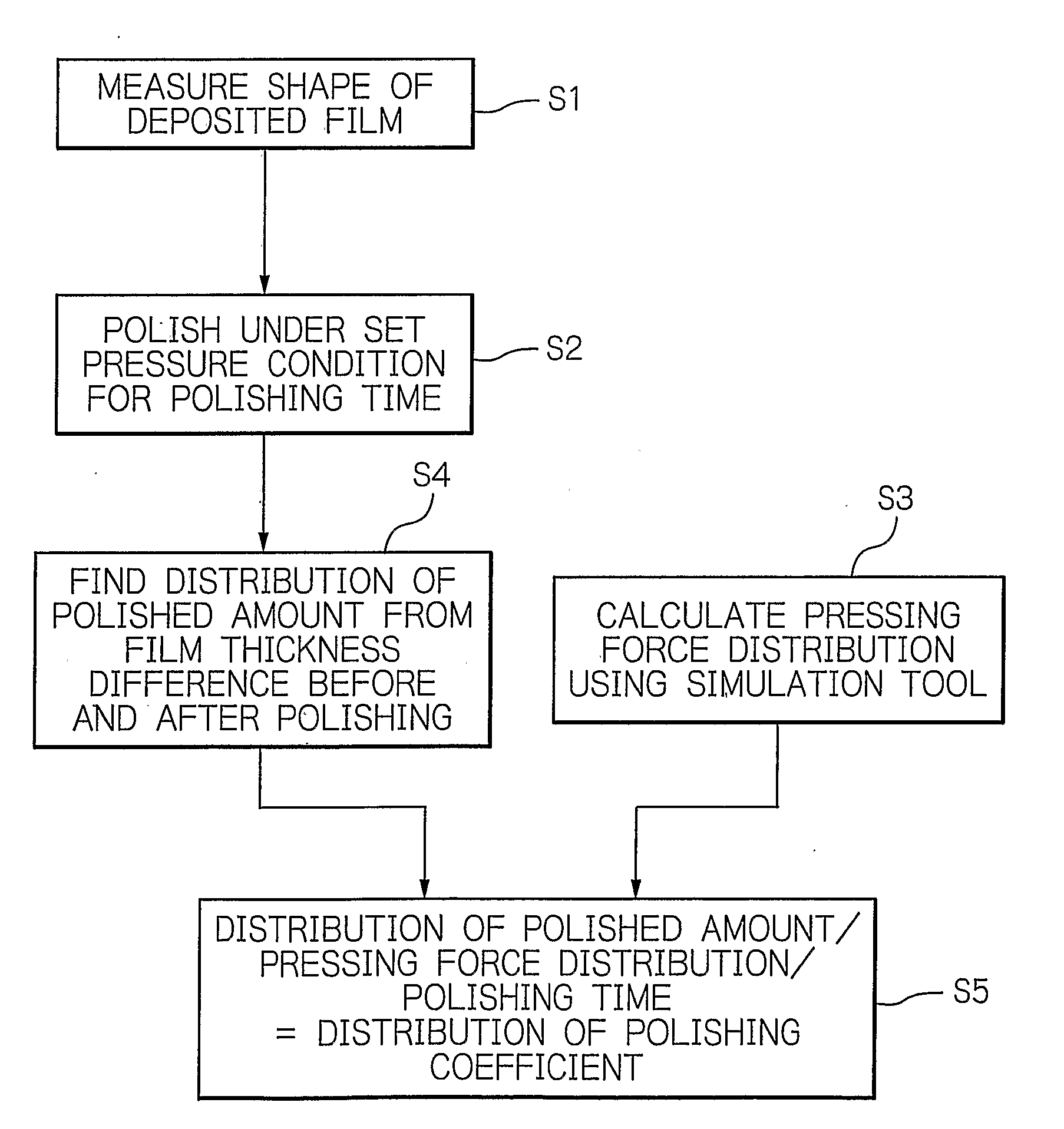
[0007]The present invention has been proposed in view of the foregoing problems, and it is an object of the invention to automatically optimize a processing pressure using a simulator based on the Preston's empirical formula within a polishing apparatus, sufficiently monitor even those parameters which cannot be covered by the Preston 's empirical formula to improve a correction accuracy, and accomplish a uniform polishing profile associated with increasing miniaturization of integrated circuits.
[0008]It is another object of the present invention to correctly manage the state of consumable materials which have been conventionally replaced after a certain number of substrates had been processed to extend the life time of the consumable materials and reduce the operational cost.
[0009]To achieve the above objects, the polishing apparatus according to the present invention comprises a top ring for holding an object to be polished such as a wafer while applying a pressure to the object to be polished against a polishing member in order to polish the object to be polished. The top ring can arbitrarily set a pressure to the object to be polished in each of concentrically partitioned areas, and can therefore control a pressing force on the object to be polished. Therefore, if the object to be polished is not polished into a flat shape, a pressing force for a required polished amount can be additionally applied, for example, to a portion which is not sufficiently polished, thus making it possible to provide high polishing performance with high accuracy flatness.

Problems solved by technology

In recent years, as semiconductor devices are increasingly more miniaturized and complicated in element structure, the semiconductor devices tend to have increased asperities and larger steps on the surface.
As a result, thin films are formed in smaller thicknesses on such steps, and open circuits can be developed due to disconnections of wires, and short circuits attributable to defective insulation between wiring layers, leading to a lower yield rate.
Specifically, allowed aging changes in the polishing profile is increasingly narrowed in more miniaturized devices and devices having a larger number of layers, resulting in a higher frequency of replacement of consumed polishing members.
However, the consumable members of the CMP are so expensive that a higher frequency of replacement due to consumption will largely affect the cost of devices.
However, in the CMP, the speed of polishing based on chemical actions is largely affected by a processing temperature, thus making it difficult in some cases to predict the polished amount with high accuracy only from the Preston's empirical formula.
Further, the Preston's empirical formula fails to cover such factors as insufficient dressing associated with a reduced cutting rate of a pad conditioner, and a reduced amount of removed polishing debris.

Method used


Image

  • Substrate Polishing Method and Apparatus
  • Substrate Polishing Method and Apparatus
  • Substrate Polishing Method and Apparatus

Examples


Embodiment Construction

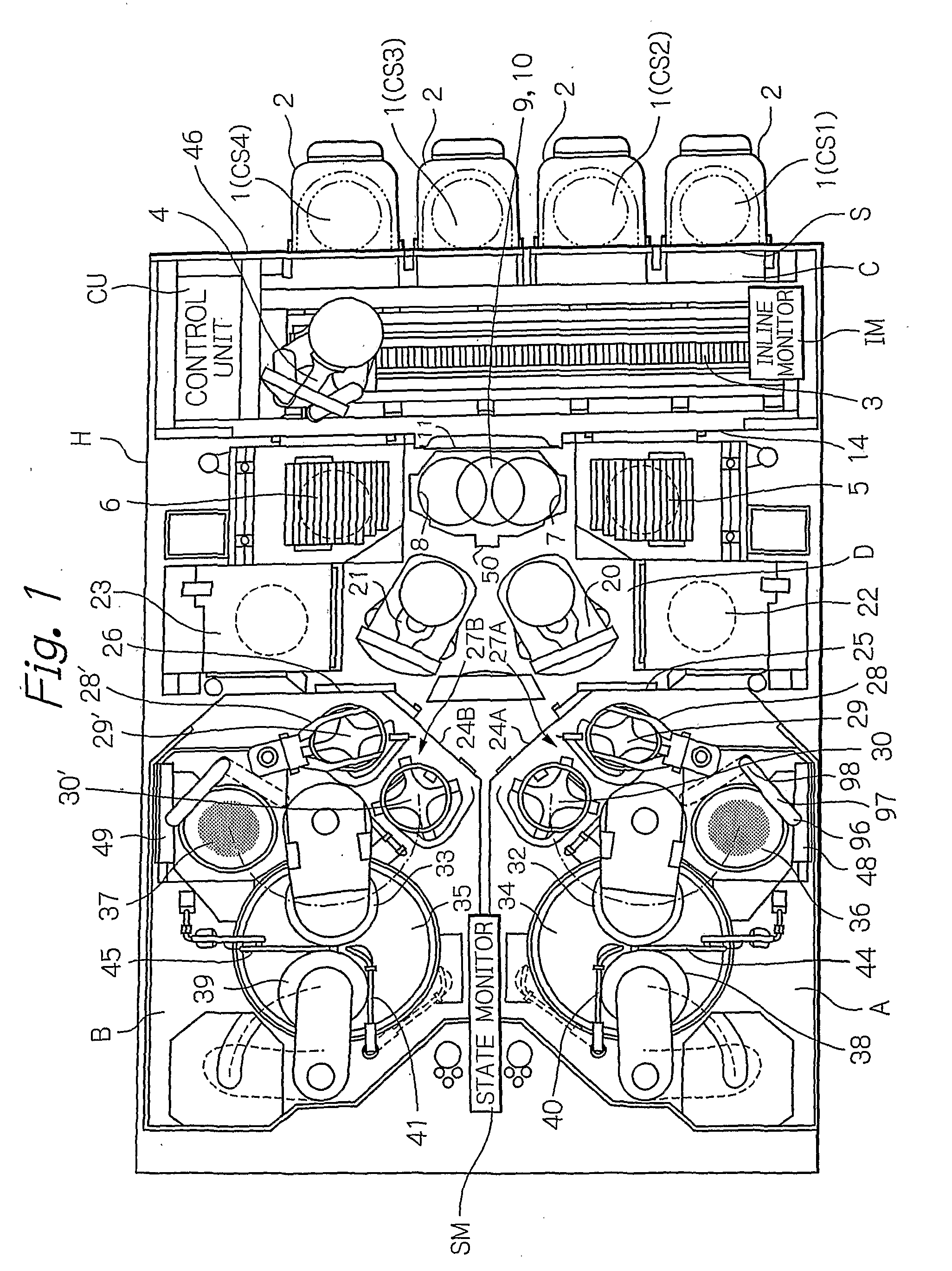
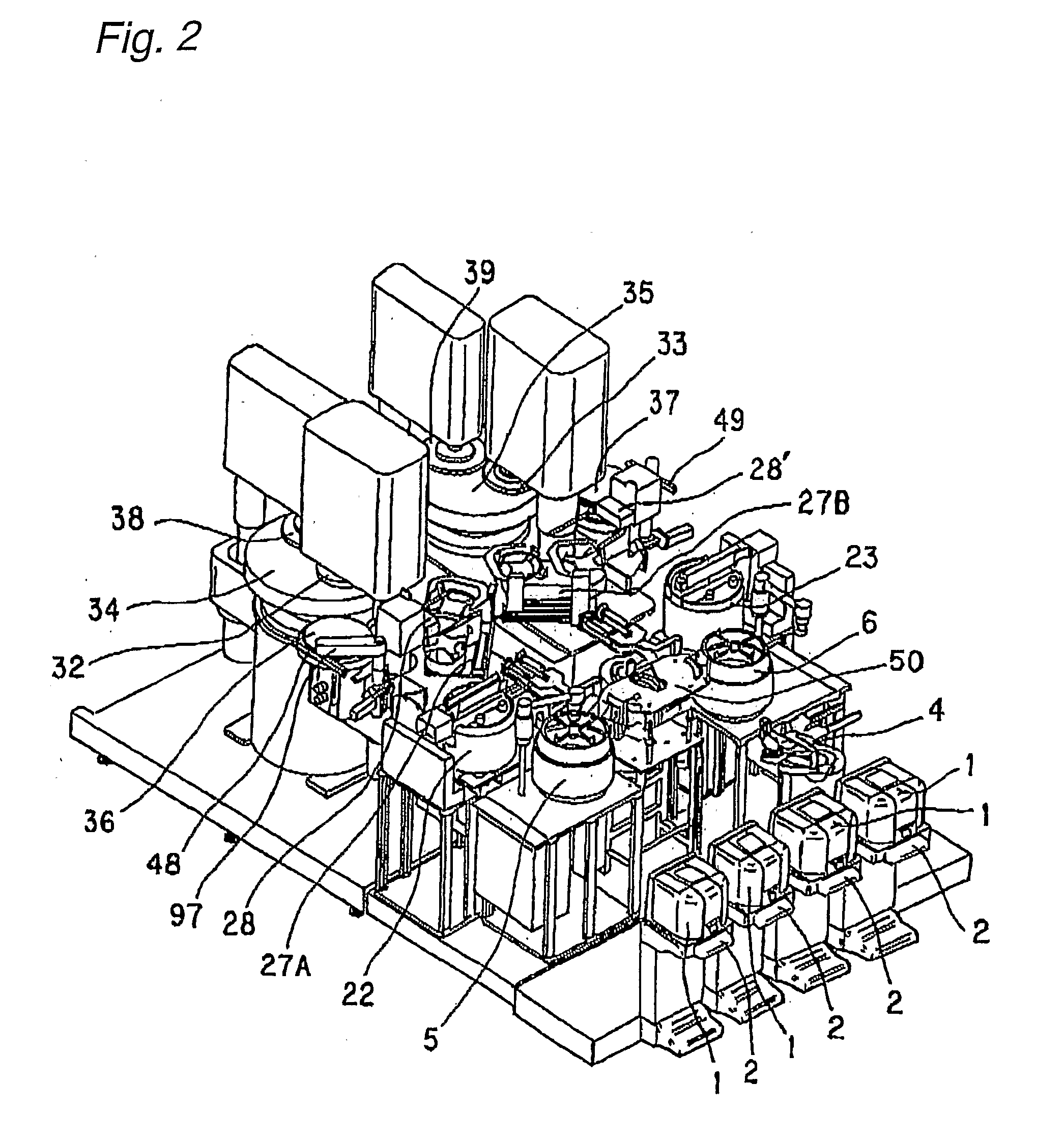
[0043]In the following, several embodiments of a polishing method and apparatus according to the present invention will be described in detail with reference to the accompanying drawings. First, one embodiment of the polishing apparatus according to the present invention will be described with reference to FIG. 1 which is a top plan view illustrating the layout and configuration of respective components in the polishing apparatus, and FIG. 2 which illustrates a perspective view of the polishing apparatus. In FIGS. 1 and 2, a transportation mechanism common to two polishing stations installed in areas A, B comprises separately installed linear transporters, each of which includes two linearly reciprocating stages that are transportation mechanisms dedicated to the two polishing stations, respectively. Specifically, the polishing apparatus illustrated in FIGS. 1 and 2 comprises four loading / unloading stages 2 for carrying wafer cassettes 1 which stock multiple wafers. A carrier robot ...


PUM


Abstract

A polishing apparatus is provided for optimizing a polishing profile in consideration of even such parameters as the temperature on the surface of an object to be polished, and the thickness of a polishing pad, in addition to a polished amount. The polishing apparatus for polishing the object to be polished under control of a control unit CU has at least two pressing sections, and comprises a top ring which can apply an arbitrary pressure to the object to be polished from each of the pressing sections, a measuring device IM for measuring a polished amount of the object to be polished, and a monitoring device SM for monitoring the object to be polished for a polishing condition. The control unit CU forces the polishing apparatus to polish the object to be polished in accordance with a simulation program for setting processing pressures required to optimize a polishing profile of the object to be polished to the top ring based on the output of the measuring device IM and the output of the monitoring device SM.

Description

TECHNICAL FIELD[0001]The present invention relates to a substrate polishing apparatus for polishing materials to be polished, represented by a semiconductor substrate, which can suppress a degradation in yield rate due to non-uniformity of residual films on the surface of substrates, mainly caused by aging changes of consumable materials, extend the life time of such consumable materials to reduce an operation cost, and a polishing apparatus which embodies the method.BACKGROUND ART[0002]In recent years, as semiconductor devices are increasingly more miniaturized and complicated in element structure, the semiconductor devices tend to have increased asperities and larger steps on the surface. As a result, thin films are formed in smaller thicknesses on such steps, and open circuits can be developed due to disconnections of wires, and short circuits attributable to defective insulation between wiring layers, leading to a lower yield rate. In a planarization technology for solving such ...

Claims


Application Information

Patent Timeline
IPC IPC(8): B24B49/00B24B49/12B24B29/02
CPCB24B49/16B24B37/30
Inventor SASAKI, TATSUYAKAMIOKA, SHINTARO
Owner EBARA CORP
Learn More