
Anti-shake apparatus

a technology of anti-shake and apparatus, which is applied in the field of anti-shake apparatus, can solve the problems of user discomfort and difficulty in perfectly removing errors such as dc offset outpu

Inactive Publication Date: 2008-06-19
ASAHI KOGAKU KOGYO KK
View PDF5 Cites 70 Cited by
  • Summary
  • Abstract
  • Description
  • Claims
  • Application Information

AI Technical Summary

Benefits of technology

[0008]Therefore, an object of the present invention is to provide an anti-shake apparatus that restrains an output of the error component from the hand-shake extent detector for the roll.

Problems solved by technology

Accordingly, the user will feel discomfort even if the degree of unnecessary inclination is very small (but not 0), especially while the user is observing the captured and inclined image on the display.
Furthermore, it is difficult to perfectly remove an error such as the DC offset output, etc.

Method used


Image

  • Anti-shake apparatus
  • Anti-shake apparatus
  • Anti-shake apparatus

Examples


Embodiment Construction

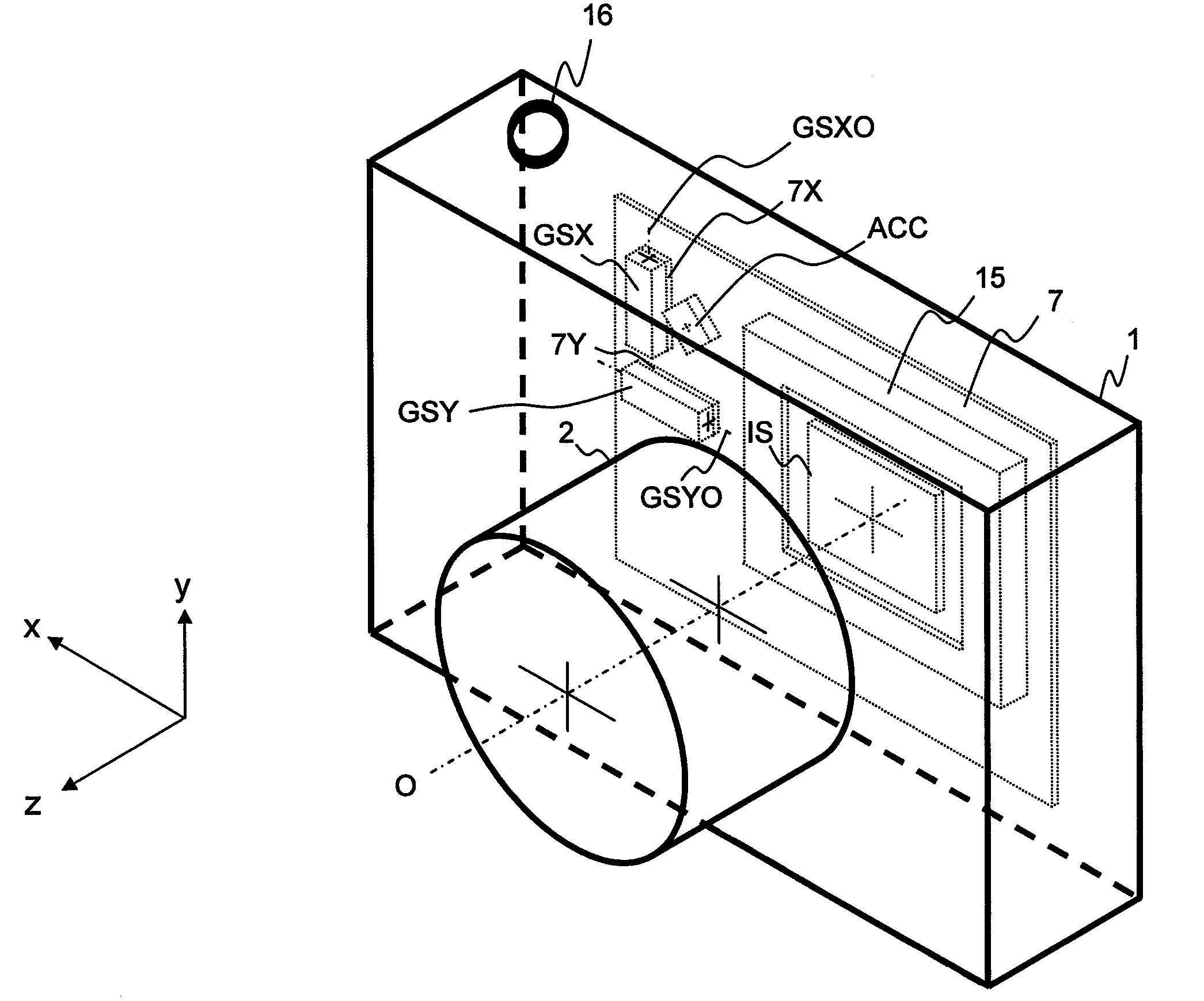
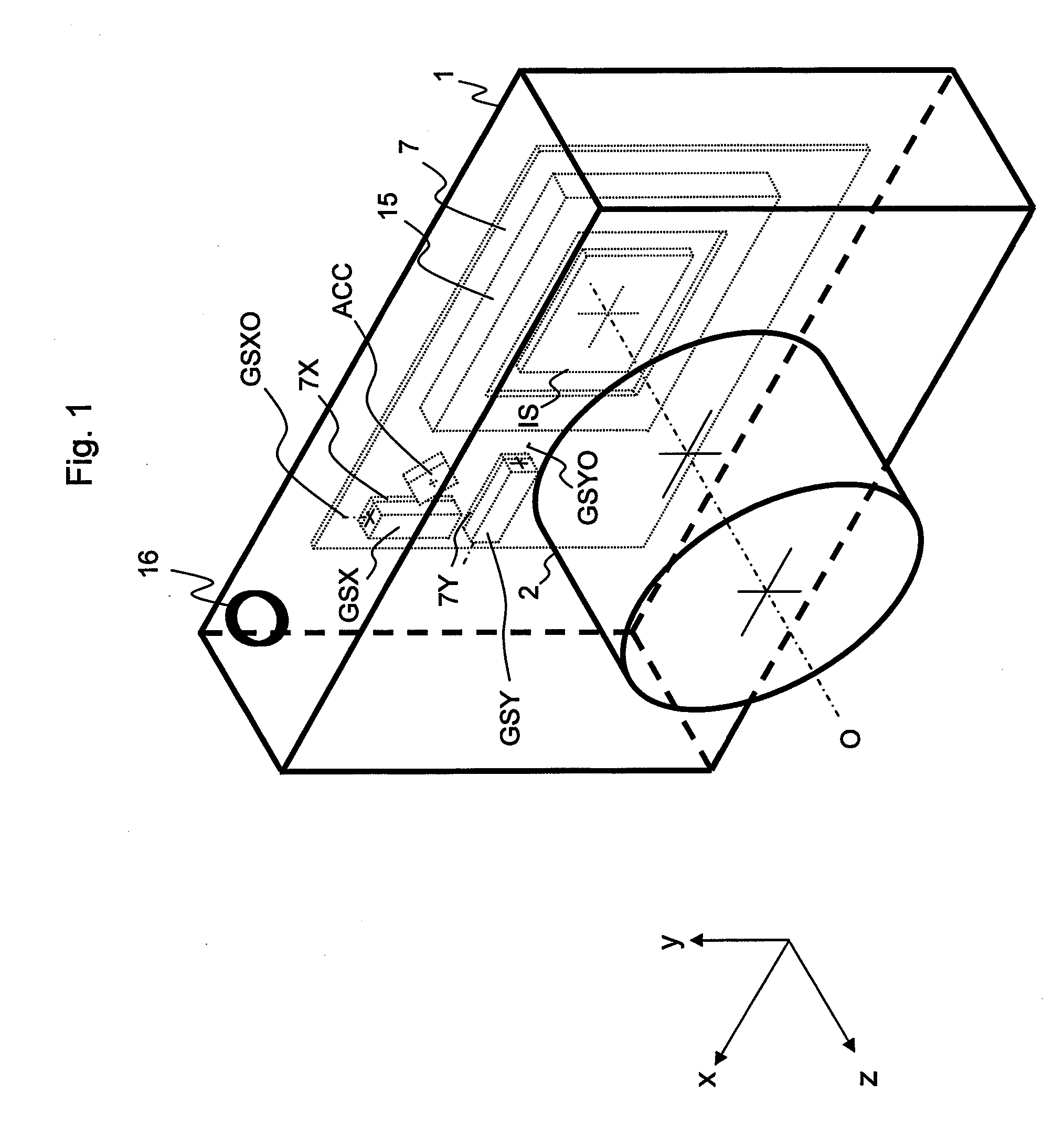
[0023]The present invention is described below with reference to the embodiment shown in the drawings. In the embodiment, the photographing apparatus 1 is a digital camera. A photographing lens (not depicted), which is included in lens barrel 2 of the photographing apparatus 1 has an optical axis O.

[0024]In order to explain the orientation in the embodiment, a first direction x, a second direction y, and a third direction z are defined (see FIG. 1). The first direction x is perpendicular to the optical axis O. The second direction y is perpendicular to the optical axis O and the first direction x. The third direction z is parallel to the optical axis O and perpendicular to both the first direction x and the second direction y.

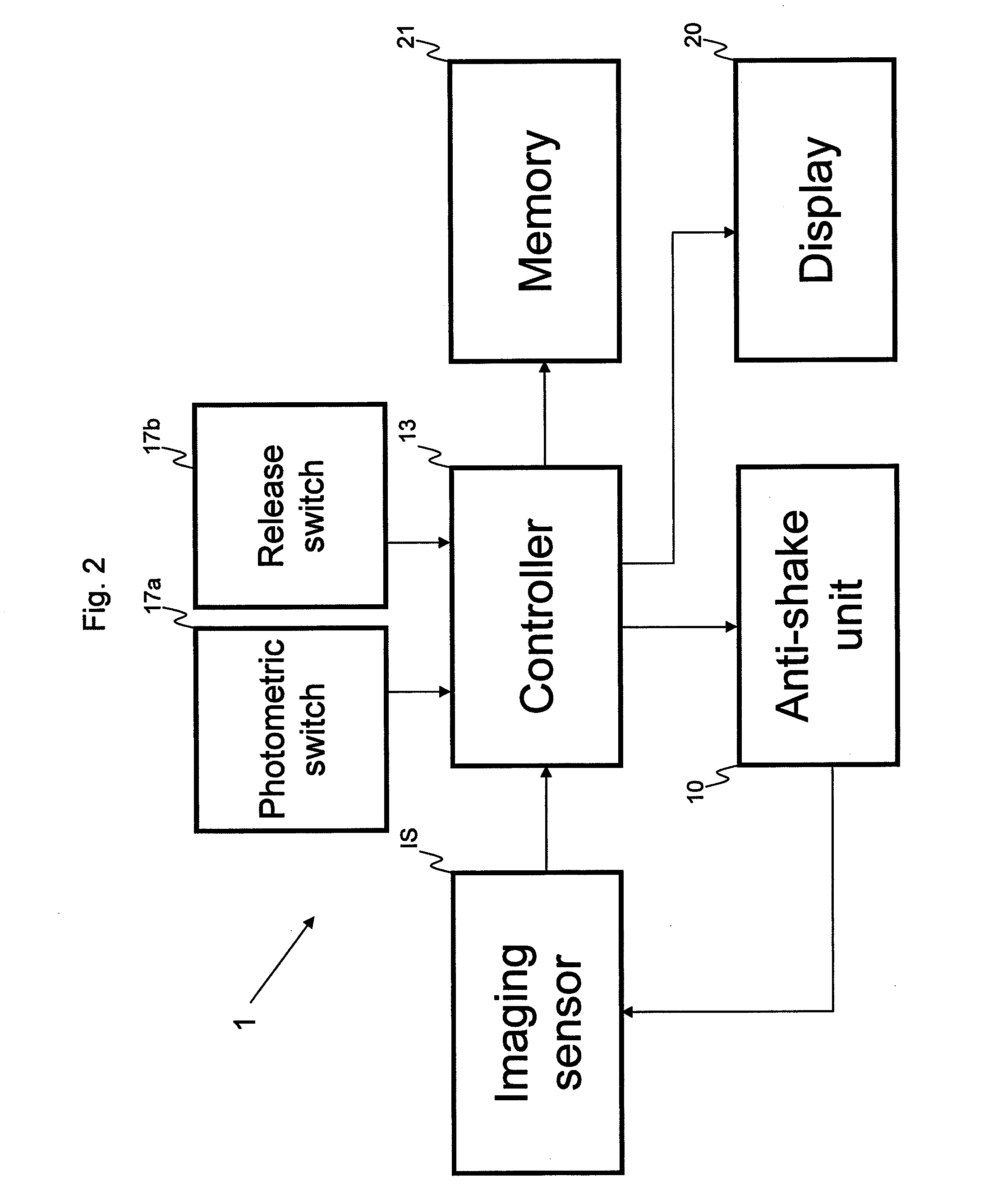
[0025]The photographing apparatus 1 has a lens barrel 2, and an imaging sensor IS (see FIG. 1). The photographing apparatus 1 also has an anti-shake unit 10, a controller 13, a display 20, and a memory 21 (see FIG. 2).

[0026]The photographic subject image is cap...


PUM


Abstract

An anti-shake apparatus for image stabilization of a photographing apparatus comprises an imaging sensor, an acceleration sensor, and an inclination degree output unit. The imaging sensor has an imaging surface on which an optical image through a photographing optical system of the photographing apparatus is captured. The acceleration sensor detects a first gravitational acceleration component in a direction of a first detection axis and a second gravitational acceleration component in a direction of a second detection axis. The first detection axis and the second detection axis are perpendicular to an optical axis of the photographing optical system. The inclination degree output unit outputs information regarding an inclination angle caused by a roll of the photographing apparatus about the optical axis, based on the first gravitational acceleration component and the second gravitational acceleration component.

Description

BACKGROUND OF THE INVENTION[0001]1. Field of the Invention[0002]The present invention relates to an anti-shake apparatus (an image-blur correcting device) for an optical apparatus, and in particular to an anti-shake apparatus that restrains an effect caused by an error characteristic of a hand-shake extent detector such as a gyro sensor etc., when an inclination caused by the roll about the optical axis is compensated for.[0003]2. Description of the Related Art[0004]An image-blur correcting device (an anti-shake apparatus) for an optical apparatus is proposed. The image-blur correcting device reduces the hand-shake effect by moving a hand-shake correcting lens or an imaging sensor on a plane that is perpendicular to the optical axis, corresponding to the amount of hand-shake which occurs during imaging.[0005]Japanese unexamined patent publication (KOKAI) No. 2005-351917 discloses an image-blur correcting device that features a hand-shake detector having a pitch gyro sensor, a rollin...

Claims


Application Information

Patent Timeline
IPC IPC(8): G03B17/00
CPCG03B5/00G03B5/08G03B2205/0007H04N5/23287H04N5/23248H04N5/23258G03B2217/005H04N23/68H04N23/6812H04N23/687
Inventor ENOMOTO, SHIGEO
Owner ASAHI KOGAKU KOGYO KK
Learn More