
Image Display Apparatus

a technology of image display and image, which is applied in the field of image display apparatuses, can solve the problems of displaced position relationship between the camera and the projection plain, displaced top-view image connections of images photographed by multiple cameras, and increased passenger numbers, so as to prevent displacement, and reliably prevent displacement at the connection of camera images

Active Publication Date: 2008-06-19
ALPINE ELECTRONICS INC
View PDF9 Cites 39 Cited by
  • Summary
  • Abstract
  • Description
  • Claims
  • Application Information

AI Technical Summary

Benefits of technology

[0014]Accordingly, an object of the present invention is to prevent displacement at a connection of camera images which is caused by tilt of the vehicle body from occurring when a composite image, such as a top-view image, is displayed.
[0015]Still another object of the present invention is to prevent displacement at a connection of camera images which is caused by tilt of the vehicle body from occurring in a composite image such as a top-view image, by using a simple configuration.
[0016]Yet another object of the present invention is to reliably prevent displacement at a connection of camera images which is caused by tilt of the vehicle body from occurring in a composite image such as a top-view image.

Problems solved by technology

However, when the vehicle body is tilted relative to the ground by passengers, the camera positions change and the positional relationship between the cameras and the projection plain is displaced.
As a result, there is a problem in that connections of images photographed by the multiple cameras are displaced in the top-view image. FIGS. 24A and 24B illustrate such a problem. FIG. 24A shows a case in which the vehicle body is not titled and FIG. 24B shows a case in which the vehicle body is tilted by θ as a result of an increase in the number of passengers in the back seats.

Method used


Image

  • Image Display Apparatus
  • Image Display Apparatus
  • Image Display Apparatus

Examples


first embodiment

A) First Embodiment

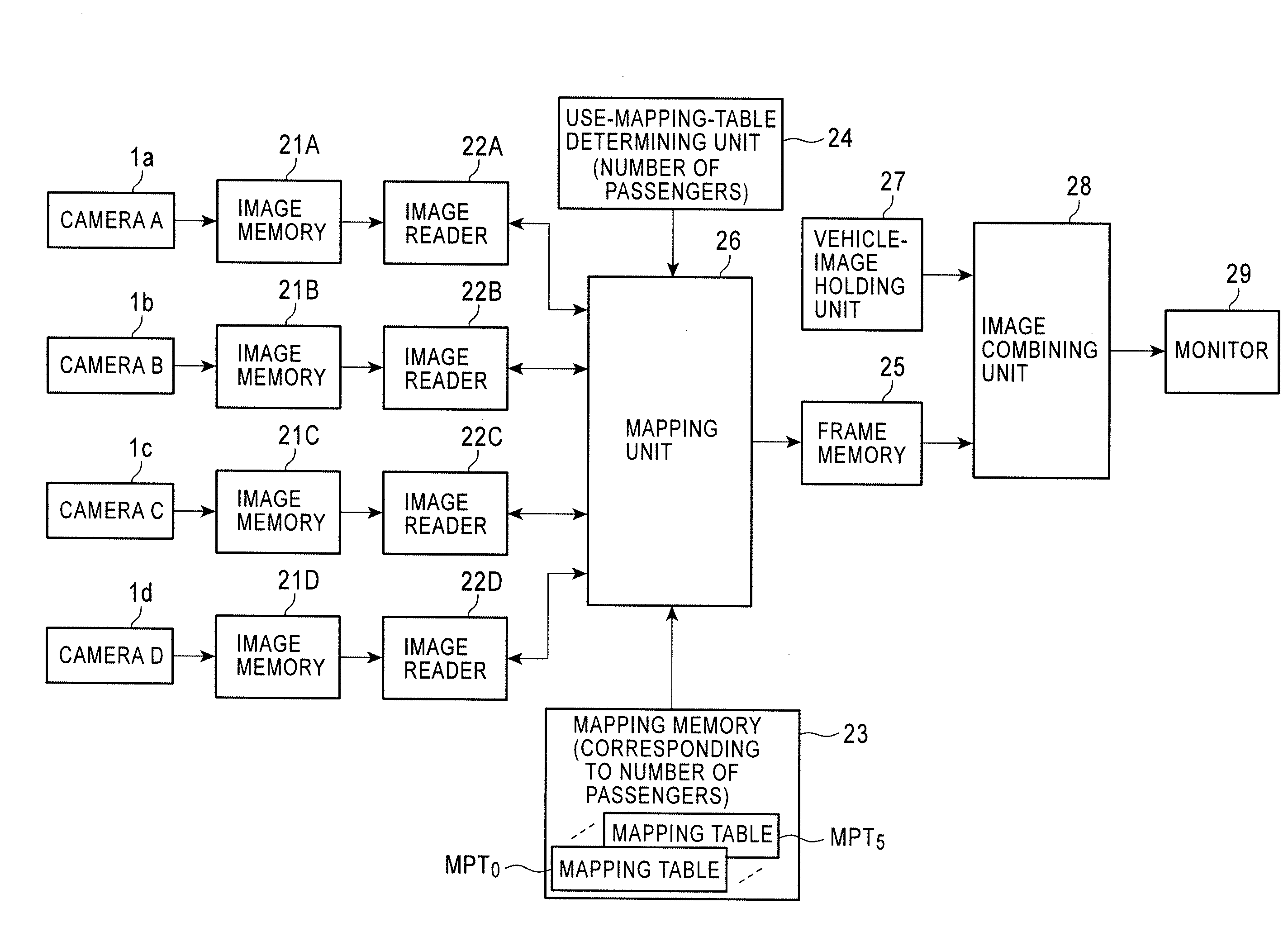
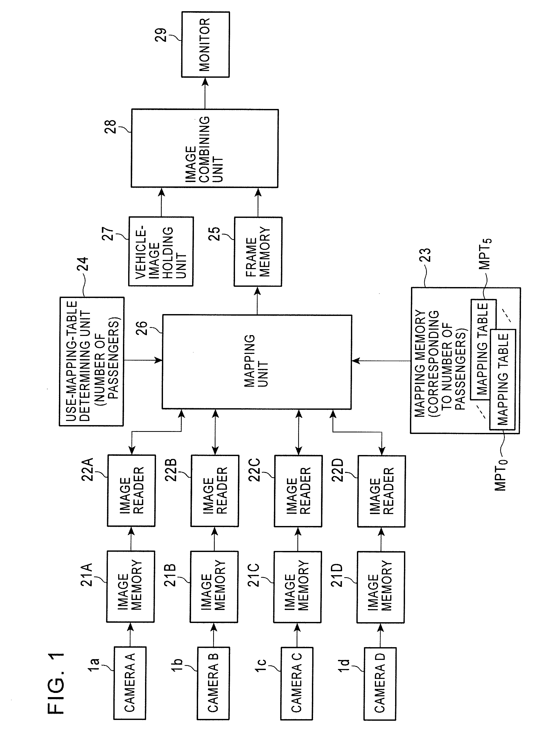
[0058]FIG. 1 is a block diagram of an image display apparatus according to a first embodiment of the present invention.

[0059]Cameras 1a, 1b, 1c, 1d are attached to a front portion, a left-side portion, a right-side portion, and a rear portion of a vehicle 2 (see FIG. 21) to photograph a landscape ahead of the vehicle, a landscape at the left side of the vehicle, a landscape at the right side of the vehicle, and a landscape behind the vehicle. The resulting photographed images are stored in corresponding camera image memories 21A to 21D. Using a fisheye lens, each of the cameras 1a to 1d can photograph a landscape in the range of 185° in front of the camera. Image readers 22A to 22D read image data from specified addresses in the image memories 21A to 21D and output the image data, respectively.

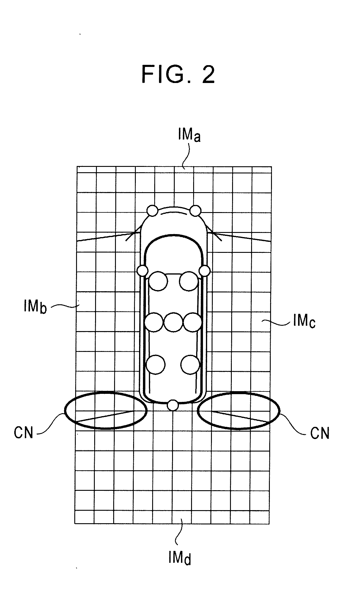
[0060]A mapping memory 23 stores multiple mapping tables MPT0 to MPT5 for mapping fisheye graphics IMa to IMd (see FIG. 22), stored in the image memories 21A to 21D, to a sc...

second embodiment

B) Second Embodiment

[0070]FIG. 7 is a block diagram of an image display apparatus according to a second embodiment of the present invention. The same units as those in the first embodiment shown in FIG. 1 are denoted by the same reference numerals. The second embodiment is different from the first embodiment in that a mapping memory 41 stores mapping tables MPT0 to MPT5 so as to correspond to the total weight W of the back-seat passengers, and a use-mapping-table determining unit 42 determines a mapping table to be used, based on the total weight W of the back-seat passengers and sends a notification indicating the determined mapping table to the mapping table 26. Since the amount of tilt of the vehicle body varies according to the total weight W of the back-seat passengers, the mapping tables are created so as to correspond to the total weight W of the back-seat passengers to prevent displacement from occurring at connections of images and are stored in the mapping memory 41.

[0071]...

third embodiment

C) Third Embodiment

[0075]FIG. 9 is a block diagram of an image display apparatus according to a third embodiment of the present invention. The same units as those in the first embodiment shown in FIG. 1 are denoted by the same reference numerals. The third embodiment is different from the first embodiment in the following points. That is, a mapping memory 51 stores multiple mapping tables MPT0 to MPT5 pre-created so as to correspond to the vehicle height, which is a distance between the vehicle body and the vehicle shaft, so as to prevent displacement at connections of images, and a use-mapping-table determining unit 52 determines a mapping table to be used according to the vehicle height, and sends a notification indicating the determined mapping table to the mapping unit 26. The amount of tilt of the vehicle body and the vehicle height change according to the back-seat passengers and baggage. Thus, the multiple mapping tables are pre-created according to the vehicle heights so as ...


PUM


Abstract

An image display apparatus combines vehicle-surroundings images photographed by cameras and displays a top view image. The image display apparatus includes image memories for storing images of landscapes ahead of the vehicle, at the left side of the vehicle, at the right side of the vehicle, and behind the vehicle which are photographed by the corresponding cameras, a mapping-table determining unit for determining a mapping table to be used by detecting the number of passengers in back seats, and a mapping unit for reading image data from the image memories by using the mapping table corresponding to the number of passengers and mapping the read image data to a frame memory to display a top view image.

Description

RELATED APPLICATIONS[0001]The present application claims priority to Japanese Patent Application Serial Number 2006-338154, filed on Dec. 15, 2006, the entirety of which is hereby incorporated by reference.BACKGROUND OF THE INVENTION[0002]1. Field of Invention[0003]The present invention relates to image display apparatuses. In particular, the present invention relates to an image display apparatus that captures surrounding images of a vehicle by using multiple cameras, combines the captured images to draw, in a frame memory, a composite image viewed from a viewpoint above the vehicle, reads image data from the frame memory, and displays the composite image.[0004]2. Description of the Related Art[0005]Systems for assisting drivers in putting vehicles into garages or parking the vehicles are under research and are also in practical use. With such an assisting system, a top-view system is known (refer to Japanese Patent No. 3300334). In the system, surrounding images of a vehicle are c...

Claims


Application Information

Patent Timeline
IPC IPC(8): H04N5/225H04N7/18
CPCB60R1/00B60R2300/102B60R2300/105B60R2300/302B60R2300/303B60R2300/304H04N7/181B60R2300/607B60R2300/8013B60R2300/806H04N5/2624H04N5/77B60R2300/402B60R1/27
Inventor ABE, KOICHINOMURA, TSUBASA
Owner ALPINE ELECTRONICS INC
Learn More