Eureka AIR delivers breakthrough ideas for toughest innovation challenges, trusted by R&D personnel around the world.

High efficiency wind turbine system

Inactive Publication Date: 2008-06-19
SHEN WEIQING +1
View PDF14 Cites 23 Cited by
  • Summary
  • Abstract
  • Description
  • Claims
  • Application Information

AI Technical Summary

Benefits of technology

[0010]A primary object of the invention is to provide a wind turbine system, which is capable of maximally trapping wind power, and efficiently converting trapped wind energy into electricity in an environmental manner.
[0011]Another object of the invention is to provide a wind turbine system, which is safe in structure for not only withstanding strong wind, but also for generating electricity with high efficiency.
[0012]Another object of the present invention is to provide a wind turbine system, which comprises an omni-directional wind-catching unit for optimally trapping wind power from all directions, and meanwhile guiding trapped wind directly onto the wind turbine so as to smooth out the airflow on the turbine. In other words, no matter the wind blow from which direction, the wind-catching unit of the present invention would effectively catch the wind and convert the wind into electricity.

Problems solved by technology

However, there is no omni-directional wind turbine disclosed within the art for maximally catching wind power from all directions.
In other words, a conventional wind turbine generator is in extreme low efficiency.
Unfortunately, when the wind blows against such conventional windmill, the blades of the windmill would have caught only less than 30% of the wind energy□while the remaining 70% of the wind energy would escape from the gaps between blades of the windmill.
What makes things worse is that the wind trapped by the blades would not always exert forces on the blades in single direction.
Therefore, low efficiency is one of fatal drawbacks of a conventional wind turbine system.
However, such methods only resulted to expensive and bulky windmills.
However, higher wind speed would also increase the risk of the windmill.
What is worse, to protect wild birds or the like, some countries or regions merely prohibit using conventional windmills in certain season.

Method used


Image

  • High efficiency wind turbine system
  • High efficiency wind turbine system
  • High efficiency wind turbine system

Examples


Embodiment Construction

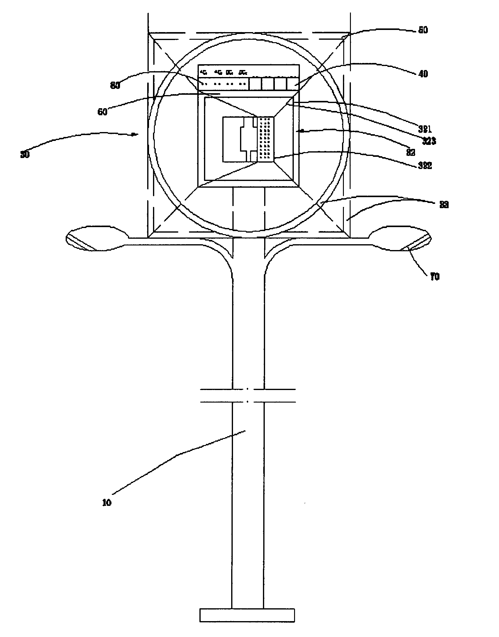
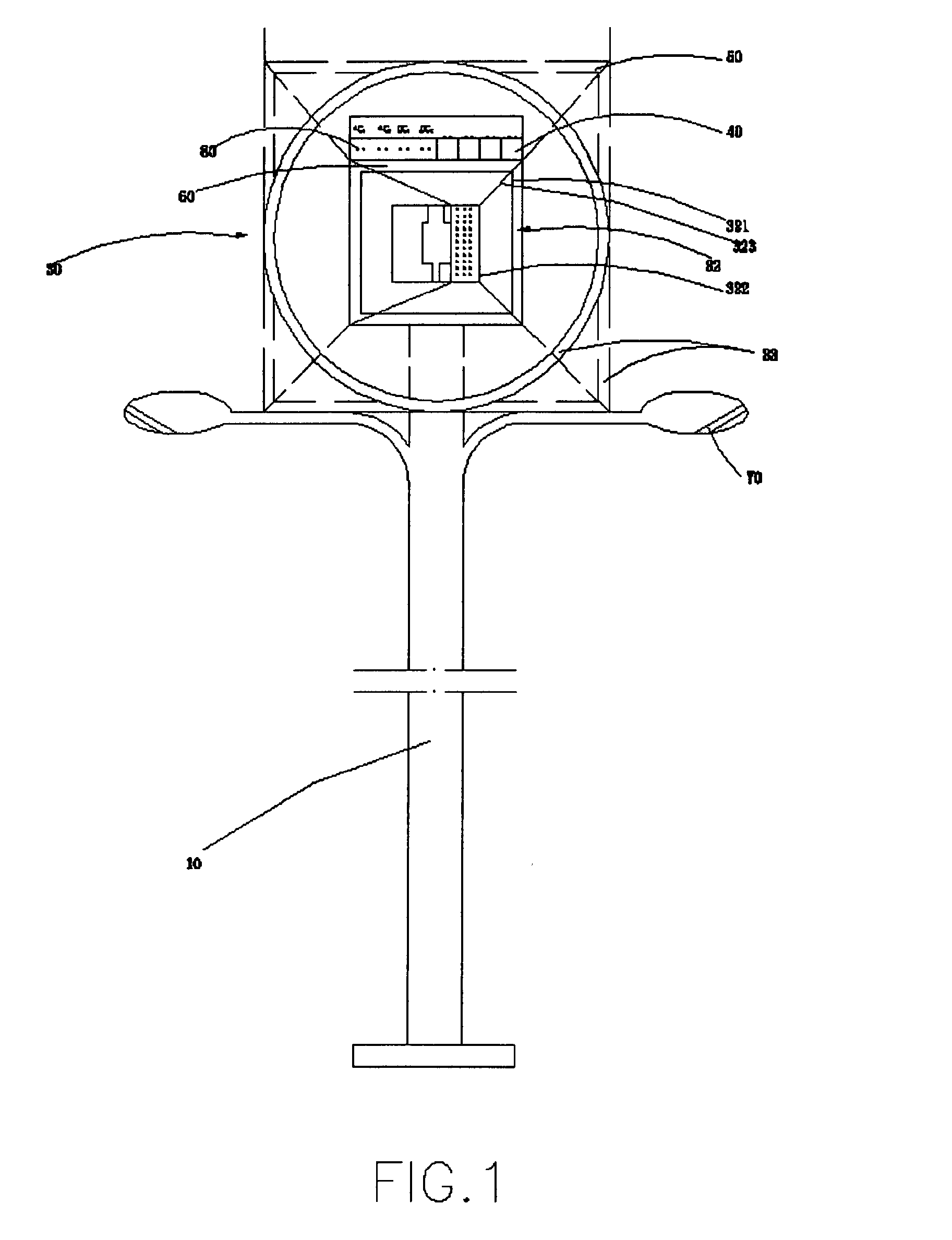
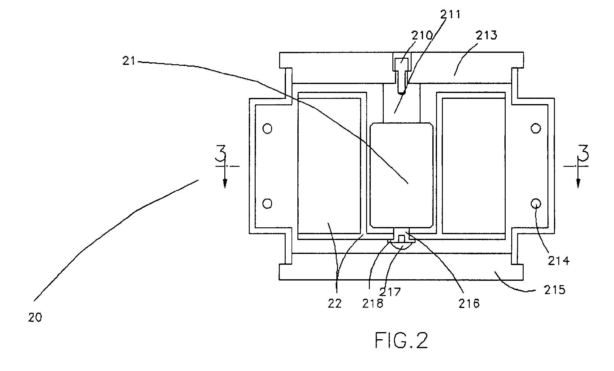
[0031]Referring to FIG. 1 and FIG. 2, the wind turbine generating system according to a preferred embodiment of the present invention is illustrated. The wind turbine generating system comprises an upright shaft 10, a wind turbine generator 20 having a generator body 21 firmly mounted onto the upright shaft 10, and a plurality of turbine blades 22 radially extended from the generator body 21, wherein the plurality of turbine blades 22 are driven to rotate with respect to said generator body to generate electricity.

[0032]Like conventional wind turbines, whenever the airflow is impacting onto the turbine blades 22, the turbine blades 22 would be driven into rotation with respect to the upright shaft 10 for electricity generation.

[0033]Referring to FIG. 1 and FIG. 4, the wind turbine generating system of the present invention further comprises a wind-catching unit 30 for circularly sheltering the wind turbine generator 20, wherein the wind-catching unit 30 comprises four wind suction c...


PUM

PropertyMeasurementUnit
Pressureaaaaaaaaaa
Angleaaaaaaaaaa
Poweraaaaaaaaaa

Abstract

A wind turbine system is disclosed, such wind turbine includes a wind turbine generator, a plurality of turbine blades radially extended from the generator and a wind-catching unit is provided for circularly sheltering the generator, wherein the wind-catching unit comprises a plurality of wind suction channels completely covering four sides and arranged in a side by side manner. Each of the wind suction channels has a wind inlet for sucking wind from outside, a wind outlet towards the generator blades, and a gradually reduced cavity communicating the wind inlet and wind outlet so as to generate a turbulent pressure between the wind inlet and wind outlet in such a manner that when wind from a direction is caught by the respective wind suction channel, the caught wind will be compressed through the gradually reduced cavity so as to effectively blow out from the wind outlet to rotate the generator.

Description

BACKGROUND OF THE PRESENT INVENTION[0001]1. Field of Invention[0002]The present invention relates to a wind turbine generating system, and more particularly, relates to a kind of high efficiency wind turbine generating system that is capable of maximally utilizing wind power from all directions and converting wind energy trapped by the wind turbine into electricity in an environmental manner.[0003]2. Description of Related Arts[0004]Electricity is traditionally generated through the burning of fossil fuel. The burning of such fuel releases greenhouse gases into the atmosphere that contributes to the global climate change and affects our environment. While generating electricity by wind energy (a kind of renewable energy) can avoid the above problem and offer a proven alternative to the burning of fossil fuel. In addition, as compared with nuclear, hydraulic, thermal power generating system, the wind turbine generating system is very economical in terms of the construction cost and o...

Claims


Application Information

Patent Timeline
IPC IPC(8): F03D9/00F03D11/00F03D9/02
CPCF03D3/0427F05B2240/13F05B2240/40F05B2240/913F05B2250/323Y02E10/74F05B2280/6013F05C2203/0882F05C2253/16Y02E10/728F05B2280/2006Y02E70/30F03D9/11F03D9/25
Inventor SHEN, WEIQINGSHEN, JIAN
Owner SHEN WEIQING
Why Eureka
Eureka Blog
Learn More