
Channel estimation method and apparatus determining a channel impulse response (CIR) distribution area using two adjacent windows

a channel impulse response and channel estimation technology, applied in the field of channel estimation methods and apparatus for determining the distribution area of channel impulse response, can solve the problems of difficult detection of cir based on a known transmission signal generated by an ofdm transmitter, difficult channel estimation, etc., to achieve accurate estimation of channels and minimize noise interference

Inactive Publication Date: 2008-06-12
SAMSUNG ELECTRONICS CO LTD
View PDF2 Cites 78 Cited by
  • Summary
  • Abstract
  • Description
  • Claims
  • Application Information

AI Technical Summary

Benefits of technology

The present invention provides a channel estimation method and apparatus that can accurately detect the channel response and minimize noise interference. The method involves detecting the CIR distribution area by scanning the signal with two windows and calculating the ratio between the average power of the first window and the average power of the second window. The ratio is then compared with a threshold value to detect the start point and the end point. The apparatus includes a linear correlator, a CIR estimator, a PN remover, a fast Fourier transform unit, a discrete Fourier transform unit, and a channel equalizer. The technical effects of the invention include improved channel estimation accuracy, reduced noise interference, and improved signal quality.

Problems solved by technology

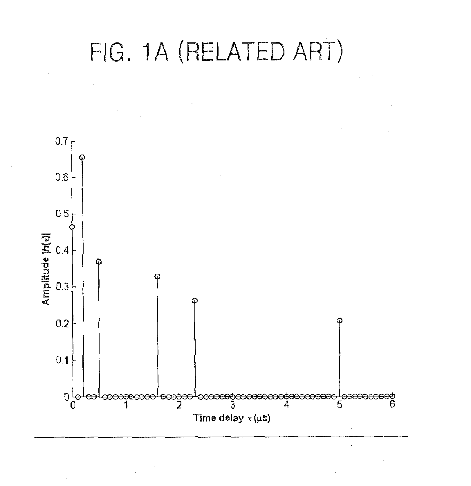
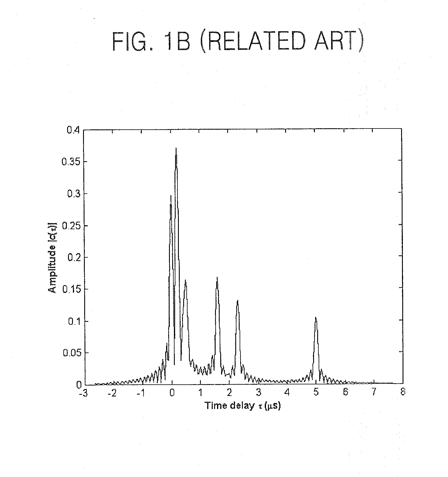
However, in addition to the transmitted information used to estimate the CIR, the received signal may also include noise such as adjacent channel interference or white Gaussian noise, which may make channel estimation difficult.
The above-mentioned CIRs being unwanted CIR components having a low-energy value may make it difficult to detect a CIR based on a known transmission signal generated by an OFDM transmitter.
1069-1072” is used, CIR detection may be difficult due to an unwanted CIR component, having a low-energy value because of inter-symbol interference (ISI) having a high-energy value and energy leakage in a channel model.

Method used


Image

  • Channel estimation method and apparatus determining a channel impulse response (CIR) distribution area using two adjacent windows
  • Channel estimation method and apparatus determining a channel impulse response (CIR) distribution area using two adjacent windows
  • Channel estimation method and apparatus determining a channel impulse response (CIR) distribution area using two adjacent windows

Examples


Embodiment Construction

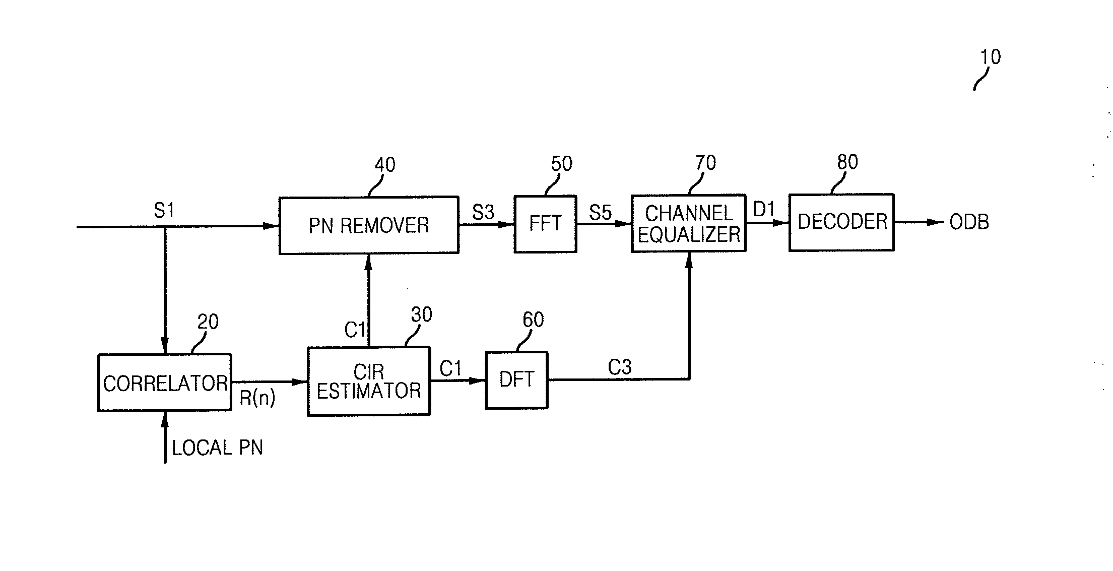
[0041]FIG. 2 is a functional block diagram of a channel estimation apparatus (or of an orthogonal frequency division multiplexing (OFDM) receiver including such a channel estimation apparatus) 10, according to an exemplary embodiment of the present invention. FIG. 3 is a graph illustrating a signal input into the channel impulse response (CIR) estimator 30 included in the channel estimation apparatus 10 illustrated in FIG. 2. FIGS. 4 and 5 are graphs illustrating the CIR area detecting operation performed by the CIR estimator 30 included in the channel estimation apparatus 10 illustrated in FIG. 2, according to alternative embodiments of the present invention.

[0042]Referring to FIGS. 2 through 5, a channel estimation apparatus 10 includes a correlator 20, a CIR estimator 30, a pseudo-noise (PN) remover 40, a fast Fourier transform (FFT) unit 50, a discrete Fourier transform (DFT) unit 60, a channel equalizer 70, and a decoder 80. The channel estimation apparatus 10 may be implemente...


PUM


Abstract

A channel estimation method and apparatus based on two adjacent windows. The channel estimation method includes scanning a signal containing noise and channel impulse response (CIR) information with a first window and a second window, detecting a CIR distribution area based on the ratio between the average power of the signal within the first window and the average power of the signal within the second window and at least one threshold value, eliminating the noise from the CIR distribution area and estimating the CIR information. Accordingly, noise interference can be minimized and accurate channel estimation can be accomplished.

Description

CROSS-REFERENCE TO RELATED PATENT APPLICATION[0001]This application claims priority under 35 U.S.C. § 119 rom Korean Patent Application No. 10-2006-0123523, filed on Dec. 7, 2006, the disclosure of which is hereby incorporated by reference herein as if set forth in its entirety.FIELD OF THE INVENTION[0002]The present invention relates to an orthogonal frequency division multiplexing (OFDM) communication system, and more particularly, to a channel estimation method and apparatus for determining a channel impulse response (CIR) distribution based on characteristics of two adjacent signal windows in a receiver in an orthogonal frequency division multiplexing (OFDM) communication system.BACKGROUND OF THE INVENTION[0003]Orthogonal frequency division multiplexing (OFDM) is a wideband modulation scheme in which a frequency bandwidth allocated for a communication session is divided into a plurality of narrow band frequency sub-bandwidths. Each narrow band frequency sub-bandwidth includes a ...

Claims


Application Information

Patent Timeline
Patent Type & Authority Applications(United States)
IPC IPC(8): H04J11/00H03D1/04
CPCH04L27/2647H04L25/0232H04L27/06H04L27/26
Inventor LIU, GUANGHUI
Owner SAMSUNG ELECTRONICS CO LTD
Learn More