
Wind-powered electricity generator

a generator and wind power technology, applied in the direction of electric generator control, wind motor with solar radiation, machines/engines, etc., can solve the problems of increasing the economic increasing the cost of petroleum and coal, and affecting the relationship between different countries, so as to achieve the effect of slowed blade rotation speed of the generator

Inactive Publication Date: 2008-06-12
LIAO CHING HAI +1
View PDF8 Cites 3 Cited by
  • Summary
  • Abstract
  • Description
  • Claims
  • Application Information

AI Technical Summary

Benefits of technology

[0007]The primary objective of the present invention is to provide a wind-powered electricity generator that can generate electricity in a breeze and rotational speed of the blades of the generator can be slowed down in a strong wind.
[0013]When the rotational speed of the rotor is lower than a predetermined lower level in a breeze, the power supply device provides electrical power to the secondary windings to produce a complementary torque on the rotor to increase the rotational speed of the rotor.
[0014]When the rotational speed of the rotor is higher than a predetermined upper level, the power supply device provides electrical power to the excited windings to produce a stall-torque on the rotor to reduce the rotational speed of the rotor.

Problems solved by technology

Because industry advances rapidly, reserves of petroleum and coal deplete gradually and economic cost of petroleum and coal also increases.
Relationship between different countries may become nervous because of bidding for energy.
If wind speed is slower than a breeze, the conventional wind-powered electricity generators cannot work because that rotation of turbines and gears of the conventional wind-powered electricity generator needs power for overcoming friction and to start the rotation.

Method used


Image

  • Wind-powered electricity generator
  • Wind-powered electricity generator
  • Wind-powered electricity generator

Examples


Embodiment Construction

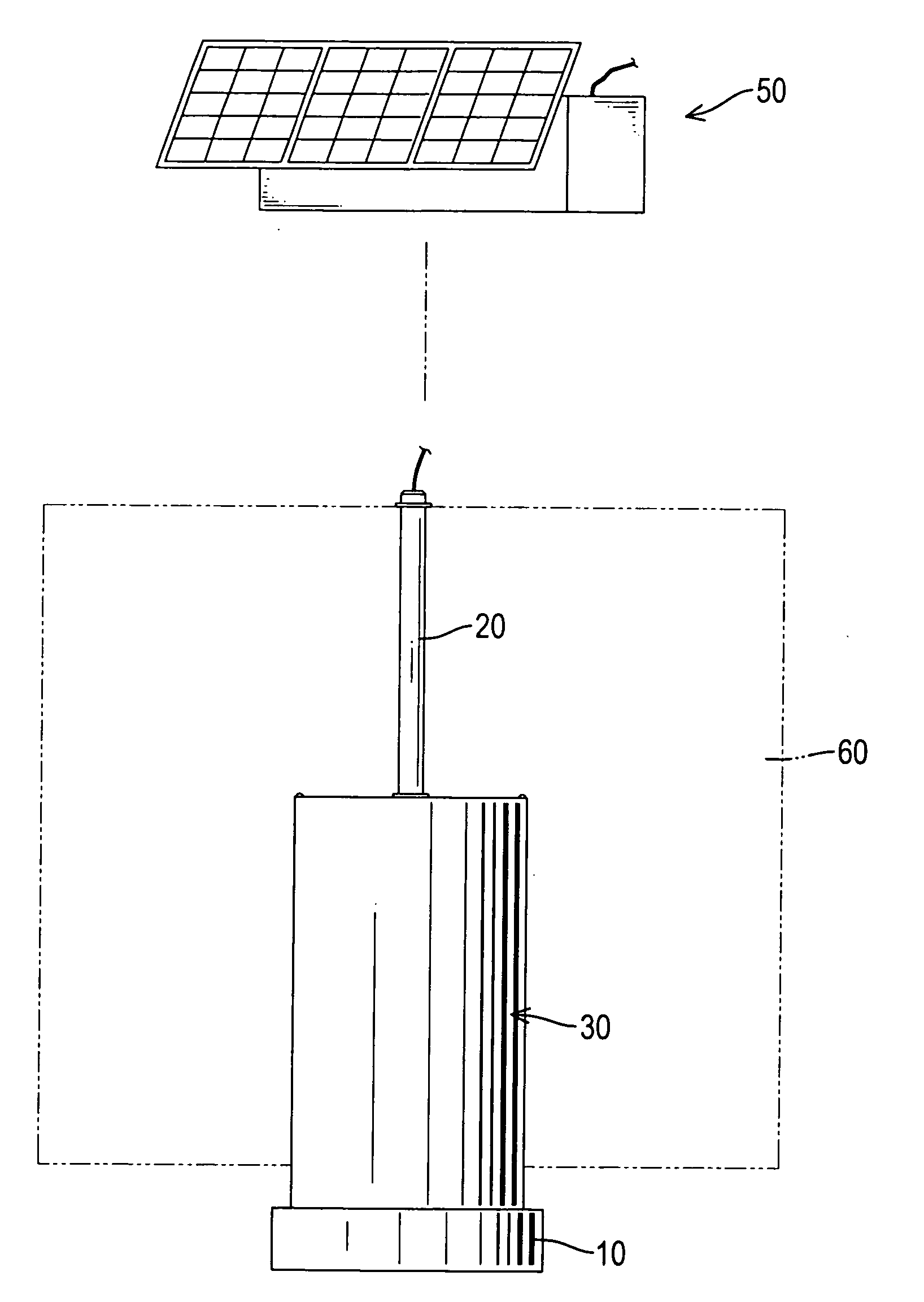
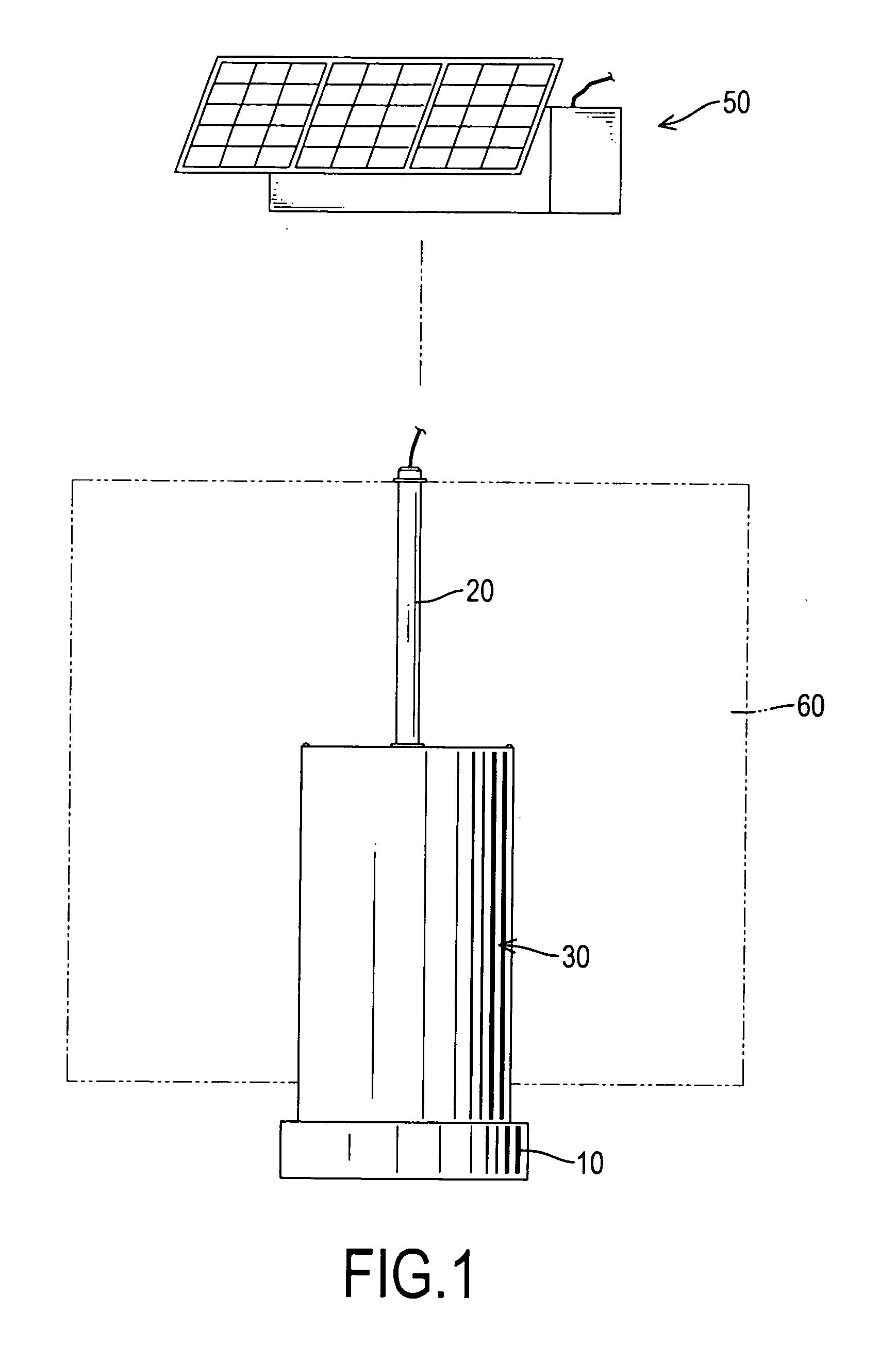
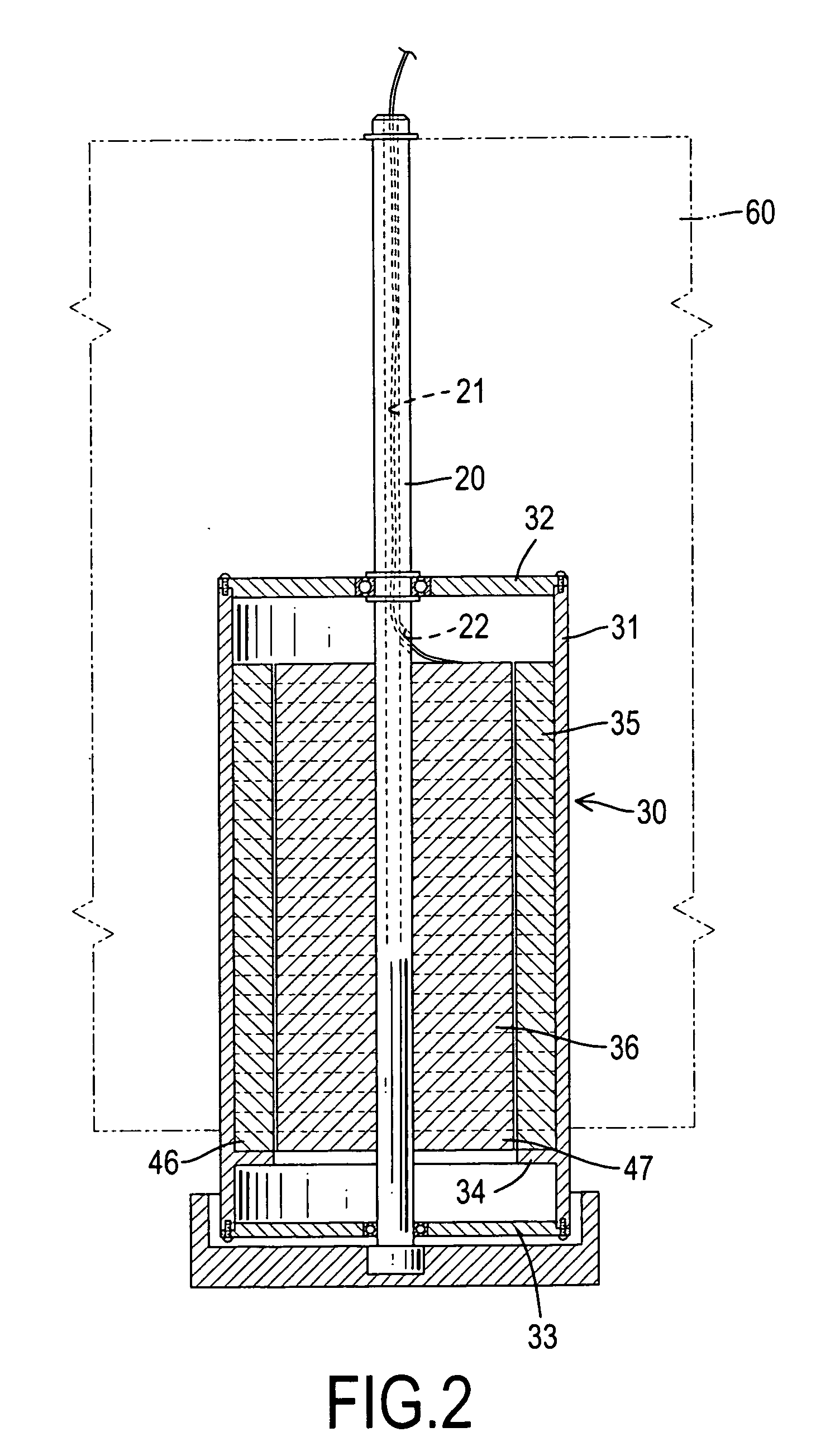
[0021]With reference to FIGS. 1, 2 and 3, a wind-powered electricity generator in accordance with the present invention comprises a base (10), an axle, a case (30), a blade assembly (60) and a power supply device (50).

[0022]The base (10) is mounted on a fixed object such as the ground.

[0023]The axle is mounted on the base (10) and has a post (20) and a stator (36). The post (20) is mounted on the base (10), is extended vertically relative to the ground and has a top, an outer surface, a connecting hole (21) and a wire hole (22). The connecting hole (21) is defined in the top of the post (20). The wire hole (22) is defined in the outer surface of the post (20) and communicates with the connecting hole (21).

[0024]With further reference to FIG. 5, the stator (36) is mounted around the post (20), is cylindrical and has a center, a through hole, an inner surface and multiple winding sets, and may be composed of a stack of silicon steel sheets (47). Thickness of the silicon steel sheets (...


PUM


Abstract

A wind-powered electricity generator includes a base, an axle, a case, a blade assembly and a power supply device. The axle is mounted on the base and has a post and stator. The stator is mounted around the post and has multiple winding sets. The winding set is mounted in the stator, arranged in a circle around the post and each winding set includes sequentially a primary winding, a secondary winding and an excited winding. The case is mounted rotatably around the stator upon the base, is hollow and has an inner surface and a rotor. The rotor is attached to the inner surface of the case, corresponds to the stator and has multiple magnets. The magnets are mounted in the rotor and arranged in a circle around the stator. The blade assembly is mounted on the outer surface of the case. The power supply device is connected to the wires of the windings.

Description

BACKGROUND OF THE INVENTION[0001]1. Field of Invention[0002]The present invention relates to a wind-powered electricity generator, and more particularly to a wind-powered electricity generator that can generate electricity in a breeze.[0003]2. Description of the Related Art[0004]Because industry advances rapidly, reserves of petroleum and coal deplete gradually and economic cost of petroleum and coal also increases. Relationship between different countries may become nervous because of bidding for energy. Therefore, technology of using renewable energy such as water, wind and solar power becomes more and more important.[0005]Conventional wind-powered electricity generators usually work when wind speed is greater than a breeze. If wind speed is slower than a breeze, the conventional wind-powered electricity generators cannot work because that rotation of turbines and gears of the conventional wind-powered electricity generator needs power for overcoming friction and to start the rota...

Claims


Application Information

Patent Timeline
Patent Type & Authority Applications(United States)
IPC IPC(8): H02P9/00F03D9/00F03D9/02
CPCF03D9/002Y02E10/725H02K7/183F03D9/25Y02E10/50Y02E10/72H02S10/12F03D9/007
Inventor LIAO, CHING-HAILIU, XI-HAI
Owner LIAO CHING HAI
Learn More