
Maximum/variable shifter widths to allow alternating phase-shift implementation for dense or existing layouts

a technology of alternating phase and width, applied in the field of integrated circuits, can solve the problems of limited space in which to place the shifter, the shifter cannot be optimized to fit in the allotted space, and the inability to vary the shifter size, so as to achieve the effect of decreasing the width of the shifter

Active Publication Date: 2008-06-05
TEXAS INSTR INC
View PDF8 Cites 136 Cited by
  • Summary
  • Abstract
  • Description
  • Claims
  • Application Information

AI Technical Summary

Benefits of technology

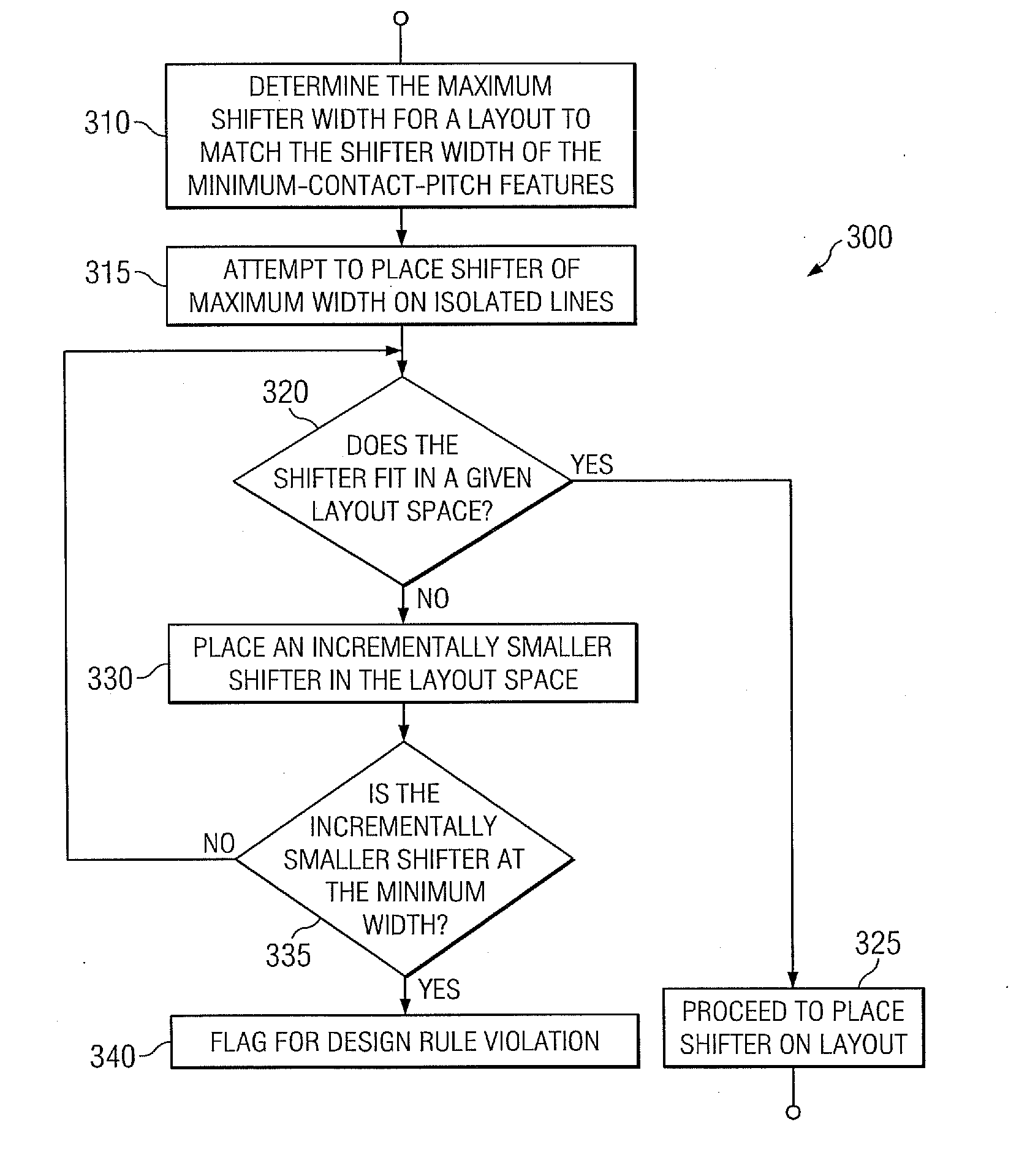
[0012]In accordance with an embodiment of the invention, there is a method of designing a lithography mask. The method can comprise determining a maximum width of a shifter, wherein the maximum width corresponds to a width of a shifter for a first set of features and determining whether the shifter having the maximum width can be placed in a shifter space for a second set of features. The method can also comprise incrementally decreasing the width of the shifter to be placed into the shifter space for the second set of features when the shifter having the maximum width cannot be placed in the shifter space for a feature in the second set of features until an acceptable shifter width can be determined or until the shifter width is reduced to a predetermined minimum shifter width.

Problems solved by technology

As such, there is a limited amount of space in which to place the shifters.
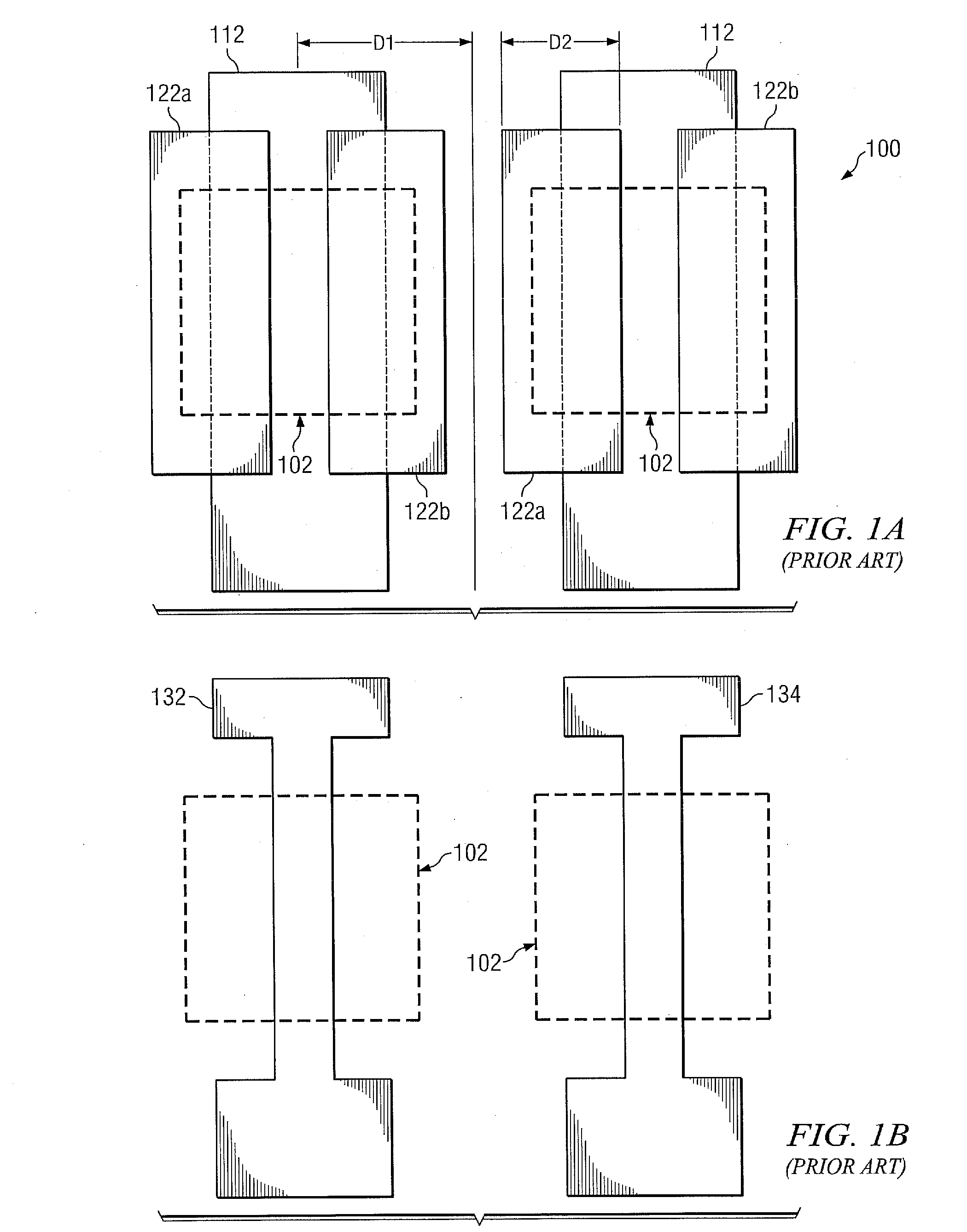
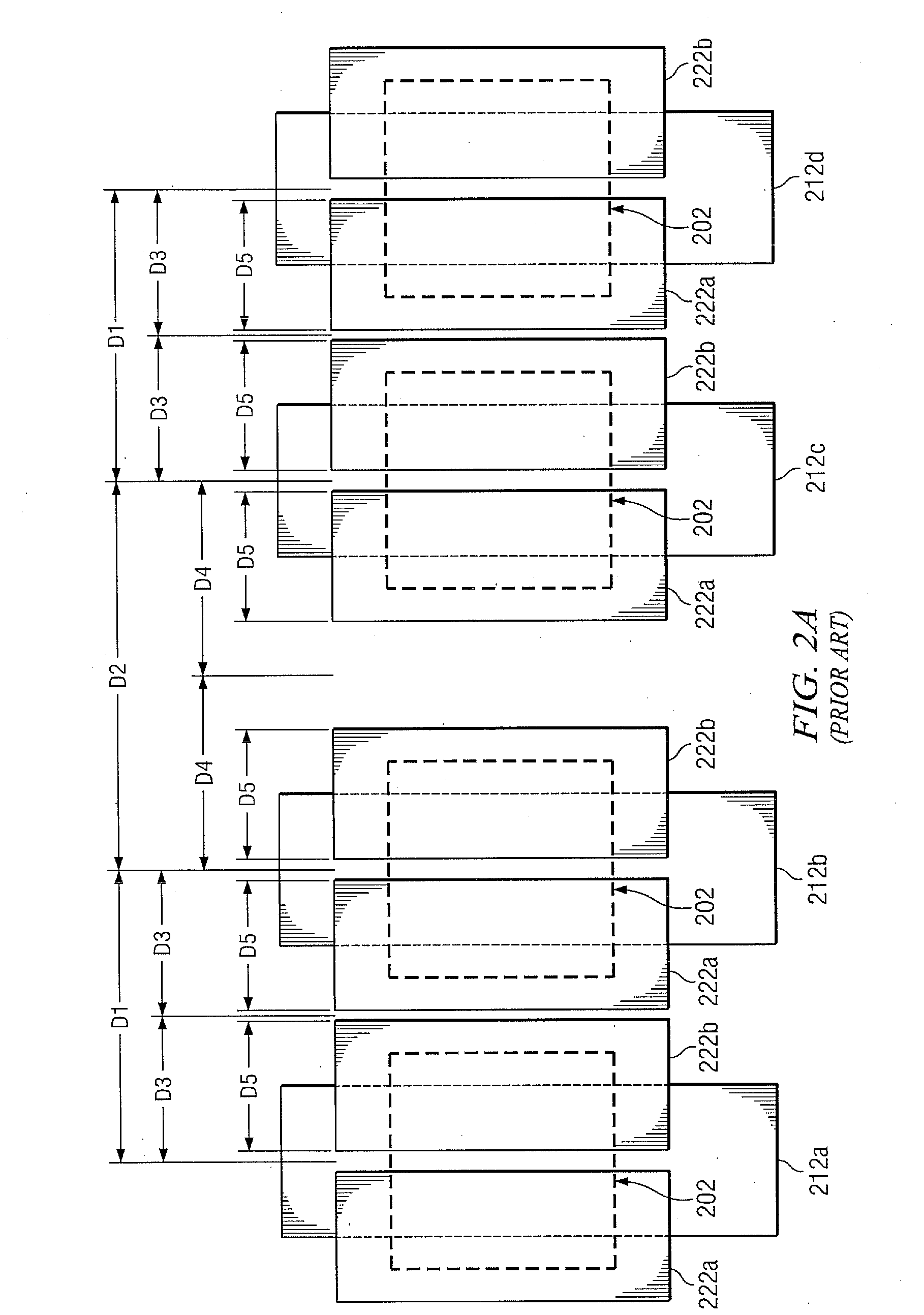
Problems arise, however, when designing an altPSM used to produce regions of a layouts having dense features and isolated features, such as arrays of transistors in random logic designs and where features are perpendicular to each other.
The conventional methods are incapable of varying the shifter size so the shifter cannot be optimized to fit in the allotted space.
Similarly, gate layout 212b is space far from gate layout 212c. The shifters having width D5 do not provide an appropriate amount of coverage, which also causes the gate features to print incorrectly.
In this case, the merged shifters cause the gate features to print incorrectly.

Method used


Image

  • Maximum/variable shifter widths to allow alternating phase-shift implementation for dense or existing layouts
  • Maximum/variable shifter widths to allow alternating phase-shift implementation for dense or existing layouts
  • Maximum/variable shifter widths to allow alternating phase-shift implementation for dense or existing layouts

Examples


Embodiment Construction

[0028]Reference will now be made in detail to the present embodiments, examples of which are illustrated in the accompanying drawings. Wherever possible, the same reference numbers will be used throughout the drawings to refer to the same or like parts.

[0029]Notwithstanding that the numerical ranges and parameters setting forth the broad scope of the invention are approximations, the numerical values set forth in the specific examples are reported as precisely as possible. Any numerical value, however, inherently contains certain errors necessarily resulting from the standard deviation found in their respective testing measurements. Moreover, all ranges disclosed herein are to be understood to encompass any and all sub-ranges subsumed therein. For example, a range of “less than 10” can include any and all sub-ranges between (and including) the minimum value of zero and the maximum value of 10, that is, any and all sub-ranges having a minimum value of equal to or greater than zero an...


PUM


Abstract

In accordance with an embodiment of the invention, there is a method of designing a lithography mask. The method can comprise determining a maximum width of a shifter, wherein the maximum width corresponds to a width of a shifter for a first set of features and determining whether the shifter having the maximum width can be placed in a shifter space for a second set of features. The method can also comprise incrementally decreasing the width of the shifter to be placed into the shifter space for the second set of features when the shifter having the maximum width cannot be placed in the shifter space for a feature in the second set of features until an acceptable shifter width can be determined or until the shifter width is reduced to a predetermined minimum shifter width.

Description

FIELD OF THE INVENTION[0001]This invention relates generally to the field of integrated circuits and more specifically to a method and system for using alternating phase-shift implementation in lithographic processes.BACKGROUND OF THE INVENTION[0002]Conventional optical projection lithography has been the standard silicon patterning technology for the past 20 years. It is an economical process due to its inherently high throughput, thereby providing a desirable low cost per part or die produced. A considerable infrastructure (including steppers, photomasks, resists, metrology, etc) has been built up around this technology.[0003]In this process, a mask, or “reticle”, includes a semiconductor circuit layout pattern typically formed of opaque chrome, on a transparent glass (typically SiO2) substrate. A stepper includes a light source and optics / lenses that project light coming through the reticle and images the circuit pattern, typically with a 4× to 5× reduction factor, on a photo-res...

Claims


Application Information

Patent Timeline
Patent Type & Authority Applications(United States)
IPC IPC(8): G06F17/50
CPCG03F1/30
Inventor BLATCHFORD, JAMES WALTERVICKERY, CARL ALBERT
Owner TEXAS INSTR INC
Learn More