Eureka AIR delivers breakthrough ideas for toughest innovation challenges, trusted by R&D personnel around the world.

Non-stop debugging apparatus for correcting errors in embedded systems and method thereof

a debugging apparatus and embedded system technology, applied in error detection/correction, instruments, computing, etc., can solve problems such as the inability to directly debug embedded systems, the inability to develop reliable systems, and the inability to degrade the integrity of source codes

Inactive Publication Date: 2008-06-05
ELECTRONICS & TELECOMM RES INST
View PDF10 Cites 22 Cited by
  • Summary
  • Abstract
  • Description
  • Claims
  • Application Information

AI Technical Summary

Problems solved by technology

As a result, since there is a demand for substantial knowledge about the hardware of the embedded systems in addition to the software, it is very difficult to develop a reliable system.
Meanwhile, since it is impossible to directly debug the embedded systems in the target due to the characteristics of the embedded systems, the debugging of the embedded systems may be performed in a remote debugging environment configured of a host and a target.
However, the method inserting the printf command or codes for monitoring has the following problems: since the codes must be directly inserted into source codes and then executed, the integrity of the source codes can be degraded; it is troublesome to prepare and execute the test program by manually changing the source codes by numbers corresponding to a total number of cases to be tested; and, in particular, in the case of the embedded systems where an environment capable of outputting the results is not built, it is difficult to use the method.
In correcting the errors in the embedded system as described above, since it is troublesome to prepare and execute the test program and it is impossible to detect the errors using the test program, a strong need exists for technology that can detect the errors in the program in real time.

Method used


Image

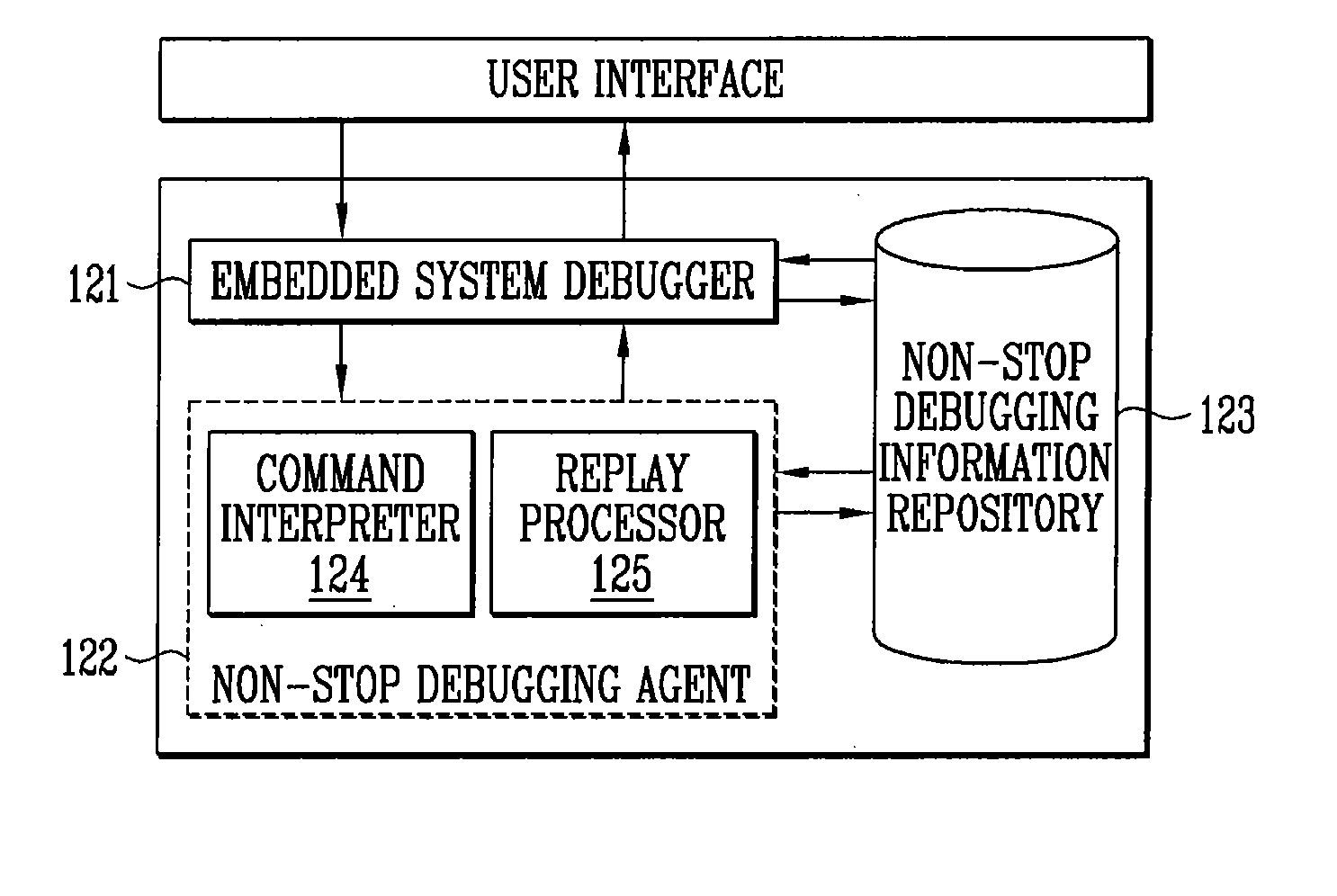
  • Non-stop debugging apparatus for correcting errors in embedded systems and method thereof
  • Non-stop debugging apparatus for correcting errors in embedded systems and method thereof
  • Non-stop debugging apparatus for correcting errors in embedded systems and method thereof

Examples


Embodiment Construction

[0020]Hereinafter, a non-stop debugging apparatus and method for correcting errors in embedded systems according to an exemplary embodiment of the present invention will be described in detail with reference to the accompanying drawings.

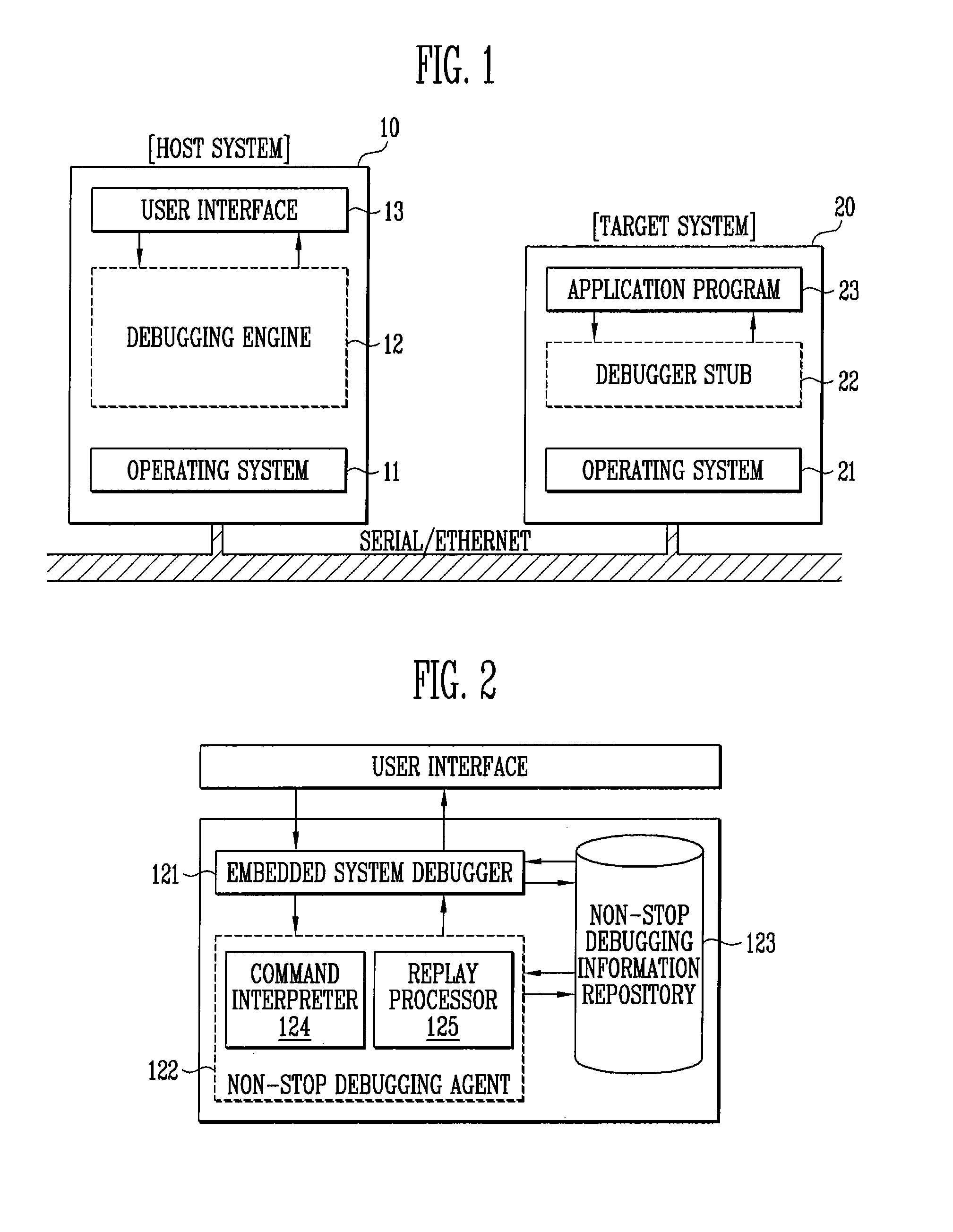
[0021]FIG. 1 is a functional block diagram showing a configuration of a non-stop debugging apparatus for correcting errors in embedded systems according to an exemplary embodiment of the present invention.

[0022]As shown in FIG. 1, since it is impossible to directly debug the embedded systems in the target due to the characteristics of the embedded systems, a debugging environment provided in the present invention is configured of a host system 10 and a target system 20, and the communication between both systems is made through the connection such as a serial or an Ethernet.

[0023]The host system 10 is configured in an operating system 11 that a developer wants to use, and is configured of a debugging engine 12 including a non-stop debugging agent (no...


PUM


Abstract

A debugging apparatus and method for correcting errors in embedded systems are provided. More particularly, a non-stop debugging apparatus and method for correcting errors in embedded systems in a development environment configured of a host and a target are provided.With the non-stop debugging apparatus and method, application programs of the embedded systems can be easily debugged without the user having to frequently execute operation and stoppage of the application programs, in time-sensitive application programs and the application programs on which it takes a user much time to perform.Also, according to the non-stop debugging apparatus and method, commands for the non-stop debugging and information required for other debugging are stored in the host system, thus making it possible to minimize the load of the target system so as to conform to the characteristics of the embedded systems sensitive to resource limitations.

Description

CROSS-REFERENCE TO RELATED APPLICATION[0001]This application claims priority to and the benefit of Korean Patent Application No. 2006-0122337, filed Dec. 5, 2006, and No. 2007-0067987, filed Jul. 6, 2007, the disclosure of which is incorporated herein by reference in its entirety.BACKGROUND[0002]1. Field of the Invention[0003]The present invention relates to a debugging apparatus and method for correcting errors in embedded systems, and more specifically, to a non-stop debugging apparatus and method capable of detecting errors in embedded systems and debugging the errors without stopping the embedded systems, in a remote development environment configured of a host and a target.[0004]The present invention is derived from research performed as a part of terminal adaptation embedded operating system technical development for mobile convergence computing for the Ministry of Information and Communication (South Korea) [Project Number: 2006-S-038-01, Project Title: Terminal Adaptation Em...

Claims


Application Information

Patent Timeline
IPC IPC(8): G06F11/00
CPCG06F11/3664
Inventor CHUN, IN GEOLLEE, CHOON OHWOO, DUK KYUN
Owner ELECTRONICS & TELECOMM RES INST
Why Eureka
Eureka Blog
Learn More