
Position sensing apparatus for radiation imaging system

a radiation imaging and position sensing technology, applied in the field of radiation imaging apparatus or system, can solve the problems of reducing the overall flexibility and portability of these x-ray systems, the solution proposed by tanaka et al. has limited value for achieving alignment between the image detection device and the radiation source, and the effect of increasing the effectiveness of the solution

Inactive Publication Date: 2008-06-05
CARESTREAM HEALTH INC
View PDF13 Cites 47 Cited by
  • Summary
  • Abstract
  • Description
  • Claims
  • Application Information

AI Technical Summary

Benefits of technology

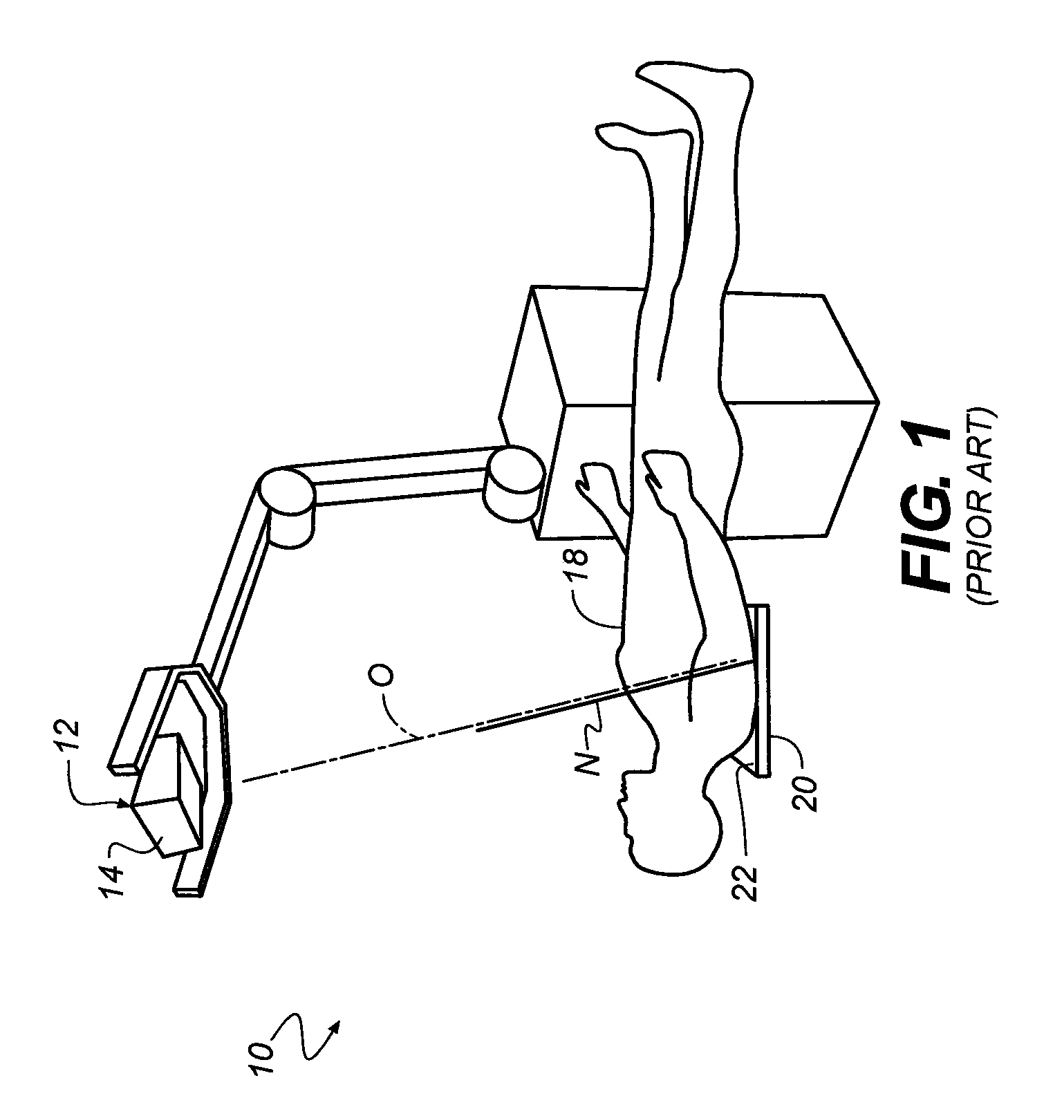
The present invention provides a radiation imaging system that includes a measurement sensor apparatus for determining the orientation of a photostimulable medium and an indicator responsive to the orientation data from the measurement sensor apparatus. The system allows for accurate alignment adjustments of the radiation head relative to the orientation of the photostimulable medium and provides data for a number of configurations. The technical effects of the invention include improved accuracy in image quality and efficiency in image processing.

Problems solved by technology

However, complex mechanical solutions of this type tend to reduce the overall flexibility and portability of these x-ray systems.
Similar to the earlier approaches that also used tilt relative to gravity, the solution proposed by Tanaka et al. has limited value for achieving alignment between the image detection device and the radiation source.
In any other orientation, however, solutions of this type become increasingly less effective as the surface of the image detection device moves away from a perfectly level orientation.
There is not enough positioning information with this type of solution for aligning the central ray of the radiation source with the normal to the surface of the image detection device.
Moreover, the particular solution proposed by Tanaka et al. does not assist the technician in making manual adjustments for tilt, but requires a more costly and trouble-prone system having motion control components.
Tilt sensing, as has been conventionally applied and as is used in the device of Tanaka et al. and elsewhere, does not provide sufficient information on cassette-to-radiation source orientation, except in the single case where the cassette is level.
Portable radiation imaging apparatus must be compact and lightweight, which makes the mechanical alignment approach such as that given in the '948 MacMahon disclosure less than desirable.
The constraint to direct line of sight alignment reduces the applicability of reflected light based methods to a limited range of imaging situations.
The complex sensor and motion control interaction required by Tanaka et al. would add considerable expense, complexity, weight, and size to existing designs, with limited benefits.
Many less expensive portable radiation imaging apparatuses do not have the control logic and motion coordination components that are needed in order to achieve the necessary adjustment.
None of these approaches gives the technician the needed information for making a manual adjustment that is in the right direction for correcting misalignment.
Significantly, none of the conventional solutions just described is particularly suitable for retrofit to existing portable radiation imaging apparatus.
That is, implementing any of these earlier solutions would be, in practice, prohibitive for all but newly manufactured equipment and would have significant cost impact.
Yet another problem not addressed by many of the conventional solutions relates to the actual working practices of radiologists and technicians.
A requirement for perpendicular delivery of radiation, given particular emphasis in Tanaka et al., is not optimal for all types of imaging.
Conventional alignment systems, while they provide for normal incidence of the central ray, do not adapt to assist the technician for adjusting to an oblique angle.

Method used


Image

  • Position sensing apparatus for radiation imaging system
  • Position sensing apparatus for radiation imaging system
  • Position sensing apparatus for radiation imaging system

Examples


Embodiment Construction

[0063]The present description is directed in particular to elements forming part of, or cooperating more directly with, an apparatus, system or method in accordance with the invention. It is to be understood that elements not specifically shown or described may take various forms well known to those skilled in the art.

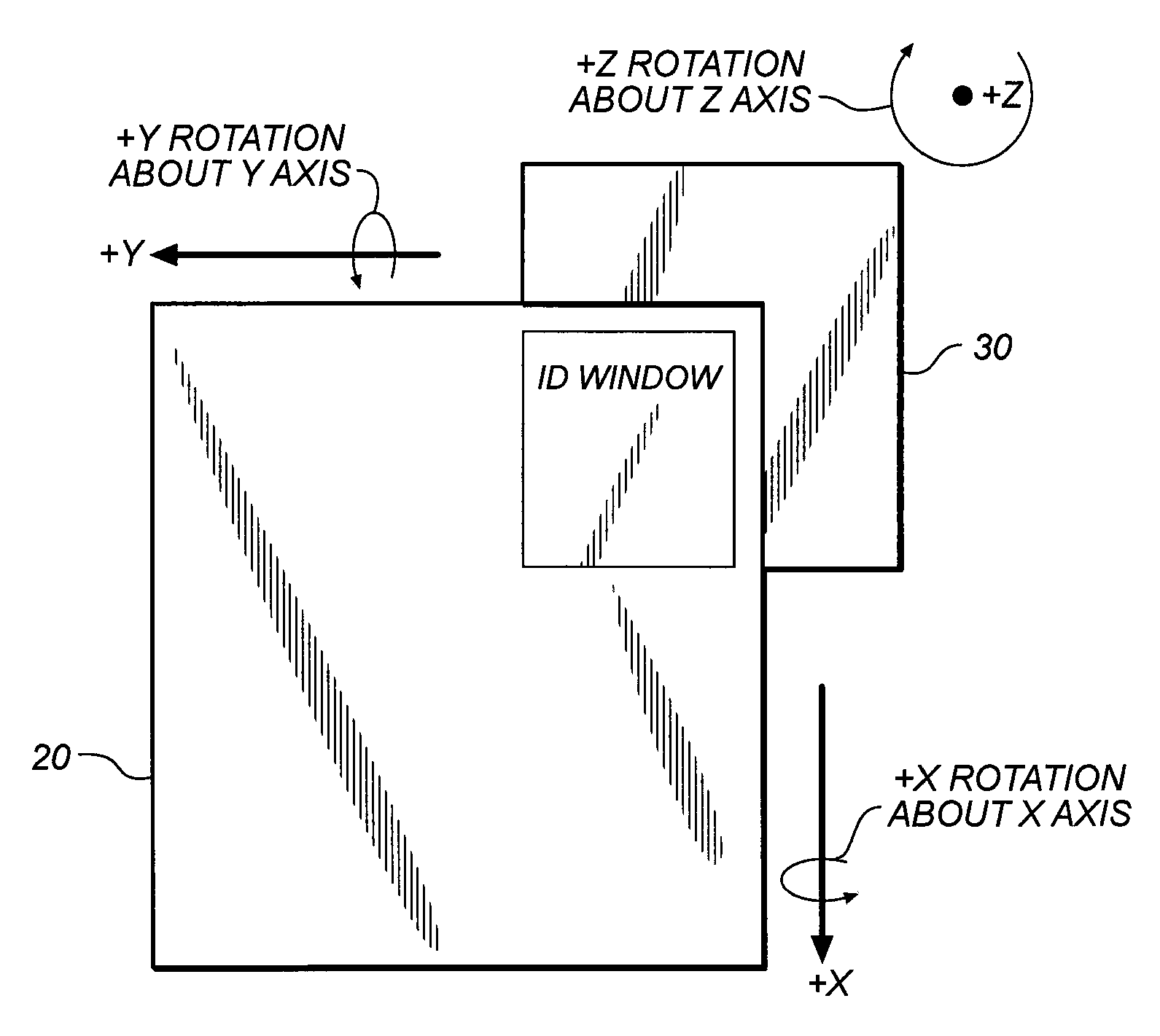
[0064]Unlike the limited tilt sensing approaches that have been used in a variety of earlier radiation imaging systems, the apparatus and method of the present invention use three-axis, preferably inertial, measurement components and techniques for obtaining object orientation data that helps to align at the proper angle a radiation source and a two dimensional radiation image detection device. Embodiments of the present invention enable the technician to position the two-dimensional radiation image detection device, also referred to in this description as a computed radiography (CR) cassette, at a favorable angle for the patient, whether in a vertical, oblique, or hor...


PUM


Abstract

A radiation imaging system includes a radiation head with a radiation source and an adjustable angular orientation. A radiation image detection device has a photostimulable medium that records an image according to radiation emitted from the radiation source. An measurement sensor apparatus, preferably inertial, is coupled to the photostimulable medium to provide three-dimensional data for determining the orientation of the photostimulable medium. There is at least one indicator responsive to the orientation data from the measurement sensor apparatus for indicating an orientation adjustment of the radiation source is needed in at least one direction.

Description

CROSS-REFERENCE TO RELATED APPLICATION[0001]This application is related to Provisional Application No. 60 / 863,976 filed Nov. 2, 2006 for Position Sensing Apparatus for Radiation Imaging System.FIELD OF THE INVENTION[0002]This invention generally relates to a radiation imaging apparatus or system; and more particularly to such an apparatus or system having inertial position sensing features for facilitating proper alignment of the radiation source relative to an image detection device for recording a radiation image.BACKGROUND OF THE INVENTION[0003]When an x-ray image is obtained, there is generally an optimal angle between the x-ray source and the usual two-dimensional receiver or image detection device that records the image data. In most cases, the x-ray source preferably provides radiation in a direction that is perpendicular to the surface of the recording medium of the receiver. For this reason, large-scale radiography systems typically mount the radiation head containing the x...

Claims


Application Information

Patent Timeline
Patent Type & Authority Applications(United States)
IPC IPC(8): A61B6/08
CPCA61B6/08A61B6/4405A61B6/547A61B6/4291A61B6/587A61B2562/0219G03B42/02A61B6/583
Inventor HEATH, MICHAEL D.LO, YAWCHENGLEVY, TERESA M.DORAN, JAMES
Owner CARESTREAM HEALTH INC
Learn More