Reduction gear mechanism and electric power steering apparatus

a gear mechanism and gear mechanism technology, applied in mechanical devices, transportation and packaging, gear details, etc., can solve the problems of rattling noise, relative speed generation between, rattling noise, etc., to reduce rattling noise, reduce relative speed, and reduce rattling noise

Inactive Publication Date: 2008-06-05
JTEKT CORP
View PDF5 Cites 2 Cited by
  • Summary
  • Abstract
  • Description
  • Claims
  • Application Information

AI Technical Summary

Benefits of technology

[0008]In order to reduce the rattling noise, backlash at the meshing section may be reduced. In this case, the rotation performance of the smaller gear and larger gear deteriorates, and the power transmission efficiency is decreased.
[0029]According to the ninth aspect, it is possible to prevent rattling noise from being generated when the steering assisting direction is switched by turning and when a reverse input load is applied to the larger gear.

Problems solved by technology

However, rattling noise is generated when the steering assist direction is switched by turning, the smaller gear is rotated reversely and a relative speed is generated between the smaller gear and the larger gear.
Moreover, with a reverse input load transmitted from the road surface to the larger gear through steering control wheels, the larger gear is slightly rotated and oscillated, and the surfaces of teeth of the larger gear and smaller gear strike each other and generate rattling noise.
In this case, the rotation performance of the smaller gear and larger gear deteriorates, and the power transmission efficiency is decreased.
However, in both cases, since the backlash is reduced, the rotation performance of the worm gear deteriorates, and the power transmission efficiency is decreased.

Method used


Image

  • Reduction gear mechanism and electric power steering apparatus
  • Reduction gear mechanism and electric power steering apparatus
  • Reduction gear mechanism and electric power steering apparatus

Examples


embodiment 2

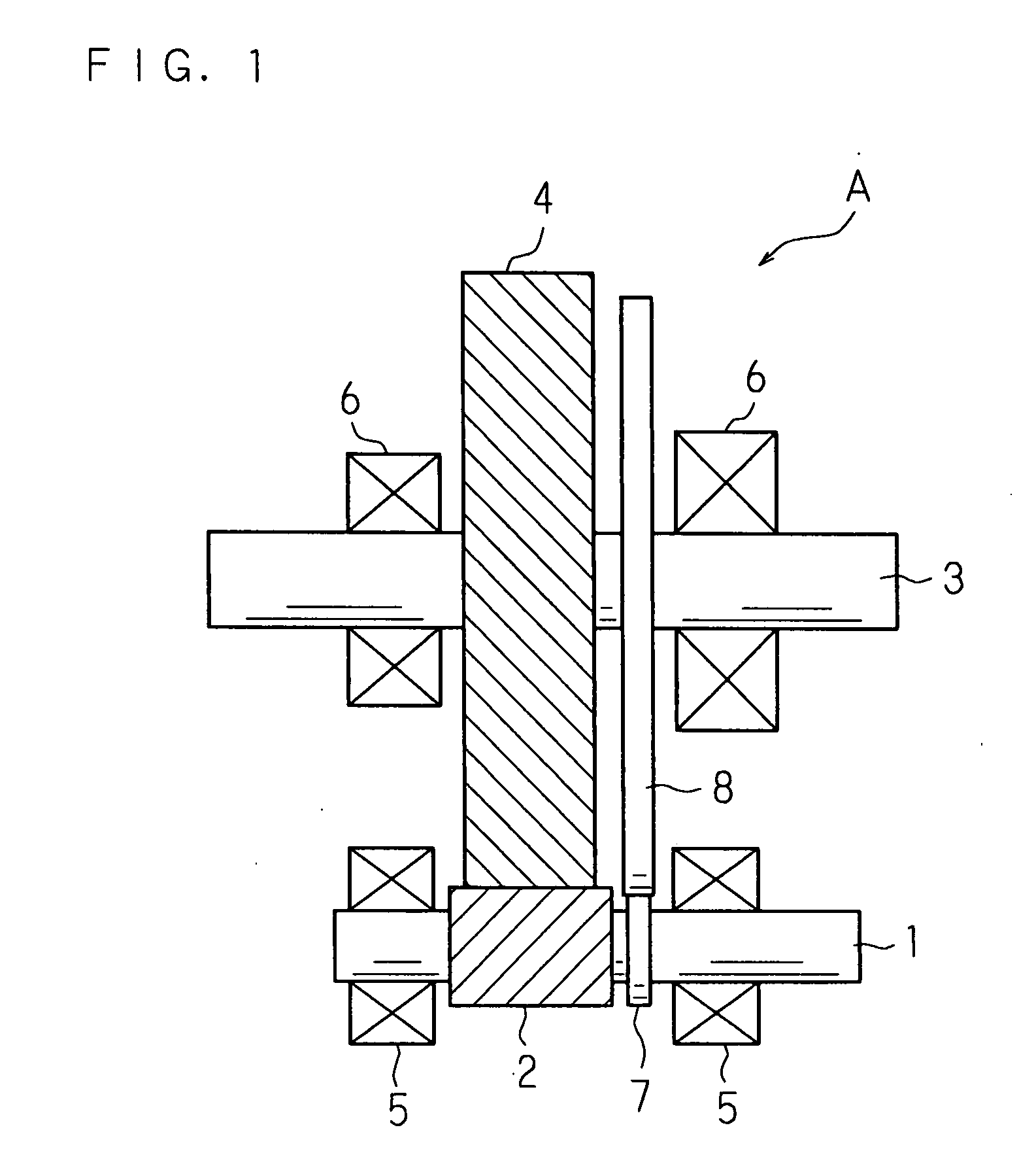
[0045]FIG. 2 is a schematic view showing other structures of essential sections of the reduction gear mechanism. In the reduction gear mechanism shown in FIG. 2, an endless belt 9 is put in a crossed pattern on the circumferential surfaces of the first and second rotors 7 and 8, instead of bringing the circumferential surfaces of the first and second rotors 7 and 8 into contact with each other.

[0046]In this embodiment, when the smaller gear 2 is rotated in one direction and the smaller gear 2 and larger gear 4 are rotated in mutually opposite directions in an interlocked manner, the torque of the first rotor 7 is transmitted from the belt 9 to the second rotor 8 without generating relative sliding between the belt 9 and the first and second rotors 7 and 8. The two rotors 7 and 8 rotate in mutually opposite directions, and a relative speed is not generated between the two rotors 7 and 8.

[0047]When one of the smaller gear 2 and larger gear 4 is rotated reversely and a relative speed i...

embodiment 3

[0049]FIG. 3 is a schematic view showing another structure of a reduction gear mechanism. In addition to Embodiment 1, the reduction gear mechanism shown in FIG. 3 further comprises a third rotor 20 which faces the second rotor 8 in the axial direction and is in contact with the circumferential surface of the first rotor 7; and a resistor 21 such as a viscous material which is interposed between the second and third rotors 8 and 20 to apply resistance to the relative rotation between the second and third rotors 8 and 20. Note that the third rotor 20 and the resistor 21 constitute a resistance section.

[0050]In Embodiment 3, the second rotor 8 is fixed to the second shaft 3, and relatively small fictional resistance force is applied between the first and second rotors 7 and 8. The third rotor 20 is composed of a disk having almost the same diameter as the second rotor 8 and loosely fitted and supported on the second shaft 3 to permit relative rotation, and larger sliding friction resi...

embodiment 4

[0057]FIG. 4 is a schematic view showing still another structure of a reduction gear mechanism. The reduction gear mechanism shown in FIG. 4 further comprises a fourth rotor 22 which faces the larger gear 4 in the axial direction and is in contact with the circumferential surface of the first rotor 7; and a resistor 21 such as a viscous material which is interposed between the larger gear 4 and fourth rotor 22 to apply resistance to the relative rotation between the larger gear 4 and the fourth rotor 22, without the second rotor 8 in Embodiment 1. Note that the fourth rotor 22 and the resistor 21 constitute a resistance section.

[0058]In this embodiment, the fourth rotor 22 is composed of a disk having almost the same diameter as the larger gear 4 and loosely fitted and supported on the second shaft 3 to permit relative rotation, and relatively large fictional resistance force is applied between the first and fourth rotors 7 and 22. Movement of the fourth rotor 22 in one direction al...


PUM


Abstract

A reduction gear mechanism includes mutually meshing smaller gear and larger gear with their shafts arranged parallel to each other; a first rotor which rotates together with the smaller gear; and a second rotor which rotates together with the larger gear, so as to generate sliding friction between the first rotor and itself in the reverse rotation direction of one of the smaller gear and larger gear. When a relative speed is generated between the smaller gear and larger gear by reverse rotation of one of the smaller gear and larger gear, resistance is applied to the reverse rotation of one of the gears and the relative speed is decreased to reduce rattling noise which is made when the surfaces of their teeth come into contact with each other.

Description

CROSS-REFERENCE TO RELATED APPLICATIONS[0001]This non-provisional application claims priority under 35 U.S.C. §119(a) on Patent Application No. 2006-249885 filed in Japan on Sep. 14, 2006 and Patent Application No. 2007-160239 filed in Japan on Jun. 18, 2007, the entire contents of which are hereby incorporated by reference.BACKGROUND[0002]1. Technical Field[0003]The present invention relates to a reduction gear mechanism including a smaller gear and a larger gear, and an electric power steering apparatus comprising the reduction gear mechanism and using an electric motor as a source of steering assist force.[0004]2. Description of Related Art[0005]An electric power steering apparatus for vehicle is constructed to detect, for example, steering torque applied to an input shaft connected to a steering wheel by the relative rotation between the input shaft and an output shaft connected coaxially to the input shaft through a torsion bar, drive a steering assist electric motor based on t...

Claims


Application Information

Patent Timeline
IPC IPC(8): B62D5/04
CPCB62D5/0412F16H2057/121F16H57/12
Inventor KUROUMARU, YOSHIKAZUKAMATANI, YASUHIROSARUWATARI, TAKEHIROOTSUKI, HIDETAKAOTSUKI, TAKUMI
Owner JTEKT CORP
Why Eureka
Try Eureka