
Downhole Tool System and Method for Use of Same

a tool system and tool technology, applied in the field of monitoring erosion in the downhole tool system, can solve the problems of abrasive wear of components within the well, need for an expensive workover, and many problems, and achieve the effect of minimizing the likelihood of failur

Inactive Publication Date: 2008-06-05
HALLIBURTON ENERGY SERVICES INC
View PDF36 Cites 37 Cited by
  • Summary
  • Abstract
  • Description
  • Claims
  • Application Information

AI Technical Summary

Benefits of technology

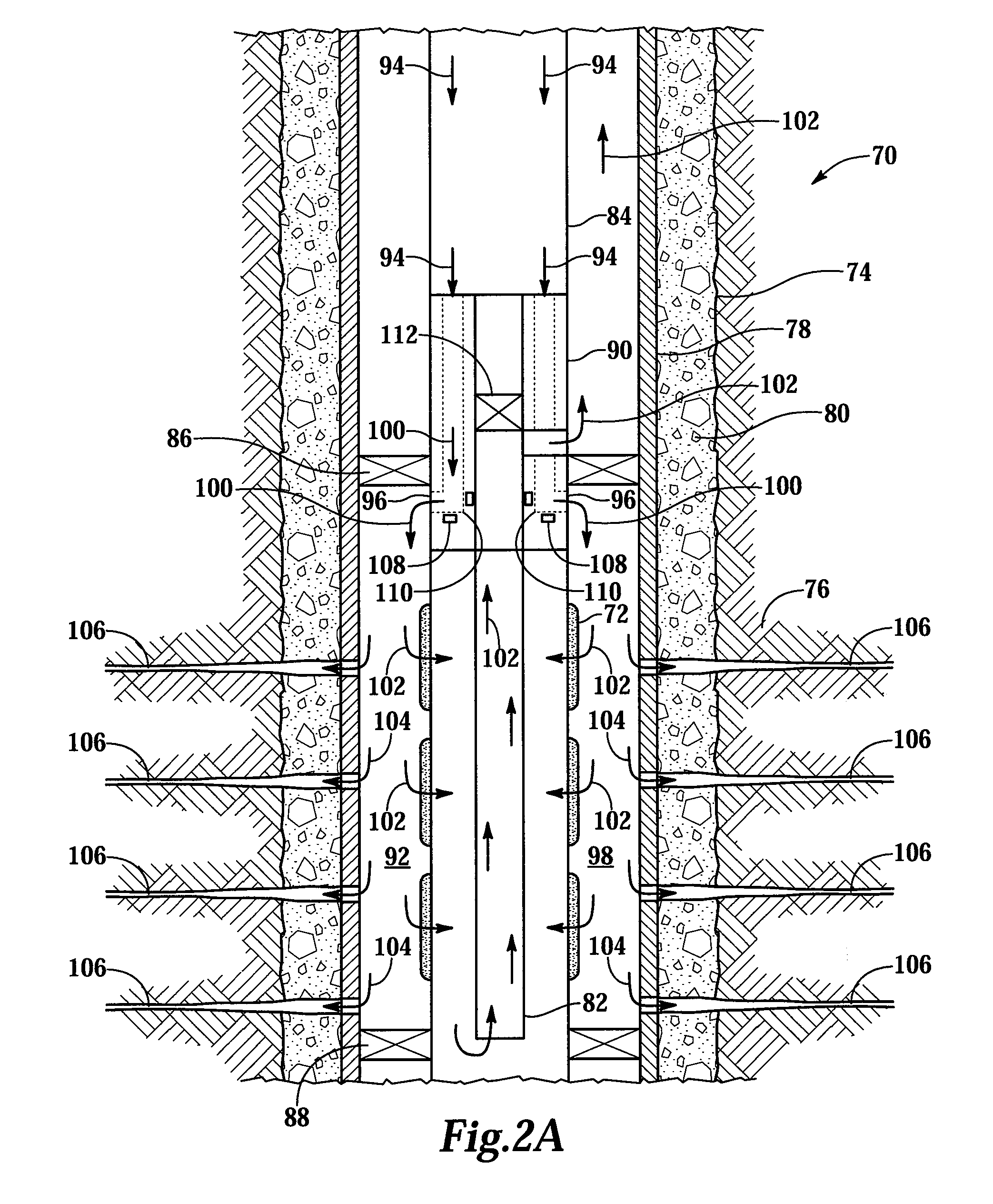
The present invention provides a system and method for monitoring erosion and the structural integrity and health of surfaces subject to erosion and wear. The system and method achieve this by monitoring erosion sensors embedded within downhole tools, downhole tubulars, flow lines, and surface equipment during wellbore construction and production operations. The sensors have a first mode in which they are responsive to RF interrogation and a second mode in which they are not responsive. The sensors transition from the first mode to the second mode upon the occurrence of a predetermined level of erosion of the downhole tool. A detector interrogates the sensors to determine whether the predetermined level of erosion has occurred and if so, the location of the predetermined level of erosion. The system and method provide a proactive approach to monitoring erosion and preventing failures caused by erosion.

Problems solved by technology

Numerous problems may occur as a result of the production of such particulates.
For example, the particulates cause abrasive wear to components within the well, such as joints, chokes, flowlines, tubulars, pumps and valves as well as any components having directional flow changes.
In addition, the particulates may partially or fully clog the well creating the need for an expensive workover.
It has been found, however, that the high injection flow rates that are associated with fracturing operations and, to a lesser extent, the particulate matter associated with both gravel and fracturing operations cause erosion to the surfaces of downhole components.
For example, the surfaces of the cross-over assembly used during these treatment operations are particularly susceptible to erosion.
In these existing solutions, a loss in pressure is a possible indication of a failure of an eroded component.

Method used


Image

  • Downhole Tool System and Method for Use of Same
  • Downhole Tool System and Method for Use of Same
  • Downhole Tool System and Method for Use of Same

Examples


Embodiment Construction

[0028]While the making and using of various embodiments of the present invention are discussed in detail below, it should be appreciated that the present invention provides many applicable inventive concepts which can be embodied in a wide variety of specific contexts. The specific embodiments discussed herein are merely illustrative of specific ways to make and use the invention, and do not delimit the scope of the present invention.

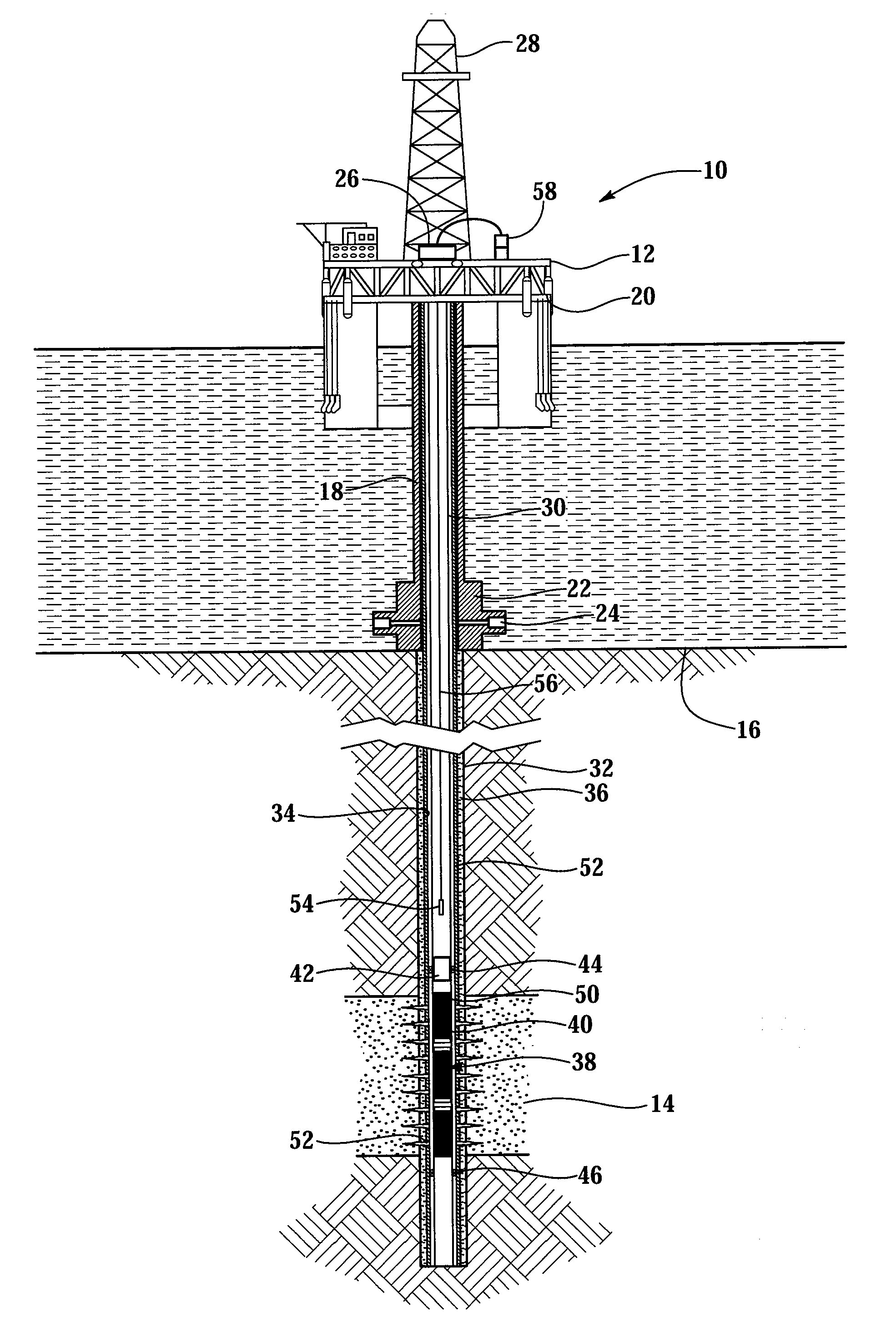
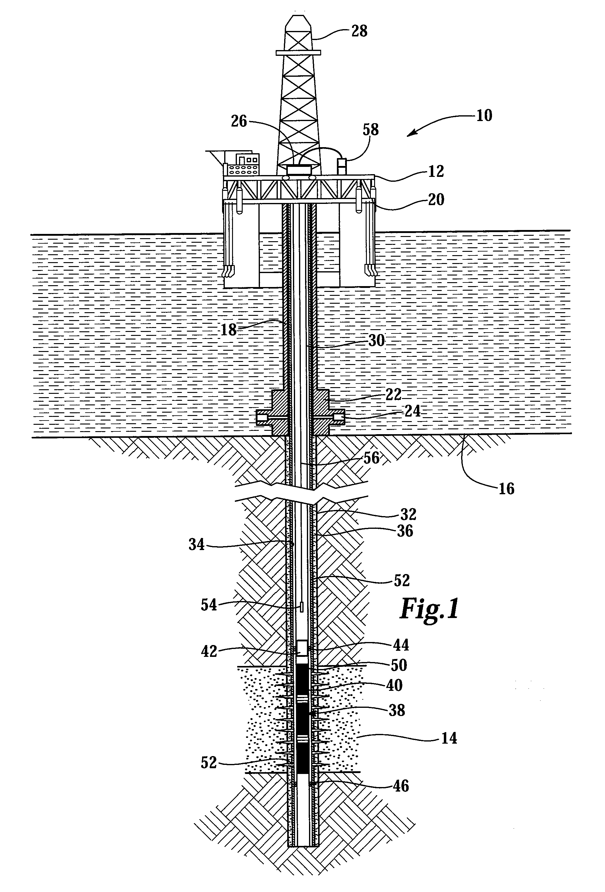
[0029]Referring initially to FIG. 1, a system for monitoring erosion of a downhole tool operating from an offshore oil and gas platform is schematically illustrated and generally designated 10. A semi-submersible platform 12 is centered over a submerged oil and gas formation 14 located below sea floor 16. A subsea conduit 18 extends from deck 20 of platform 12 to wellhead installation 22 including blowout preventers 24. Platform 12 has a hoisting apparatus 26 and a derrick 28 for raising and lowering pipe strings such as workstring 30.

[0030]A wellbore 3...


PUM

PropertyMeasurementUnit
erosionaaaaaaaaaa
radio frequencyaaaaaaaaaa
lengthaaaaaaaaaa

Abstract

A downhole tool system includes a downhole tool operably positionable within a wellbore and a sensor positioned within the downhole tool. The sensor has a first mode and a second mode. In the first mode, the sensor is responsive to RF interrogation. In the second mode, the sensor is not responsive to RF interrogation. The sensor is operable to transition from the first mode to the second mode upon the occurrence of a predetermined level of erosion of the downhole tool proximate the sensor. A detector is operably positionable relative to the downhole tool and in communicative proximity to the sensor. The detector interrogates the sensor to determine whether the predetermined level of erosion has occurred.

Description

CROSS-REFERENCE TO RELATED APPLICATIONS[0001]This is a continuation application of co-pending application Ser. No. 10 / 841,780, entitled System and Method for Monitoring Erosion, filed on May 7, 2004.TECHNICAL FIELD OF THE INVENTION[0002]This invention relates, in general, to monitoring erosion in a downhole tool system and, in particular, to use of a sensor that is interrogated downhole to determine the erosive effects caused by flowing fluids containing formation sand, gravel, proppants or other erosive agents through downhole tools.BACKGROUND OF THE INVENTION[0003]It is well known in the subterranean well drilling and completion art that relatively fine particulate materials may be produced during the production of hydrocarbons from a well that traverses an unconsolidated or loosely consolidated formation. Numerous problems may occur as a result of the production of such particulates. For example, the particulates cause abrasive wear to components within the well, such as joints, ...

Claims


Application Information

Patent Timeline
Patent Type & Authority Applications(United States)
IPC IPC(8): E21B12/02E21B47/00G01N17/00G01N23/00
CPCE21B47/00E21B47/006
Inventor DAGENAIS, PETE C.DE JESUS, ORLANDOLI, LIPING
Owner HALLIBURTON ENERGY SERVICES INC
Learn More