
System and method for reducing power consumption when heating a fuel injector

a technology of fuel injector and power consumption, which is applied in the direction of liquid fuel feeders, machines/engines, mechanical equipment, etc., can solve the problems of increasing the complexity of controlling the valve under varying operating conditions, increasing the current capacity of current sources, and increasing the power required to operate the injector, so as to improve the process of heating fuel injectors and improve the response. the effect of instantaneous electrical current and improved injector performan

Active Publication Date: 2008-06-05
FORD GLOBAL TECH LLC
View PDF26 Cites 20 Cited by
  • Summary
  • Abstract
  • Description
  • Claims
  • Application Information

AI Technical Summary

Benefits of technology

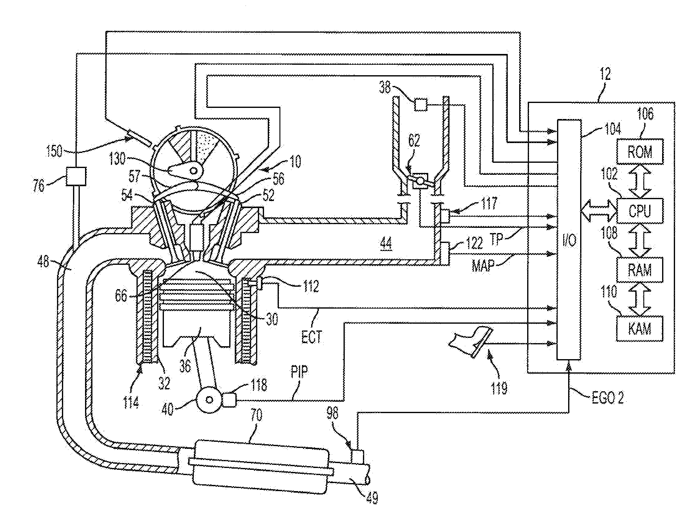
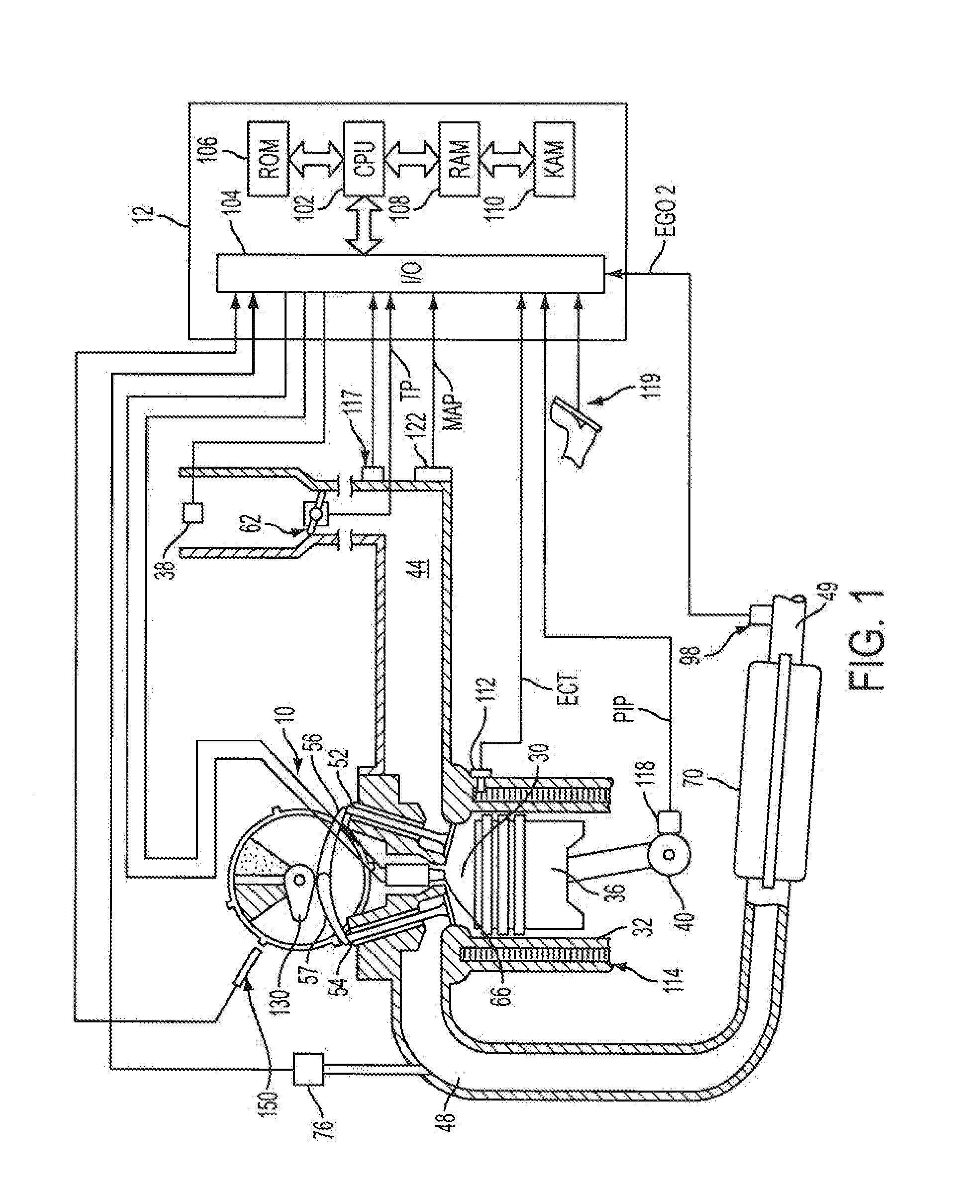
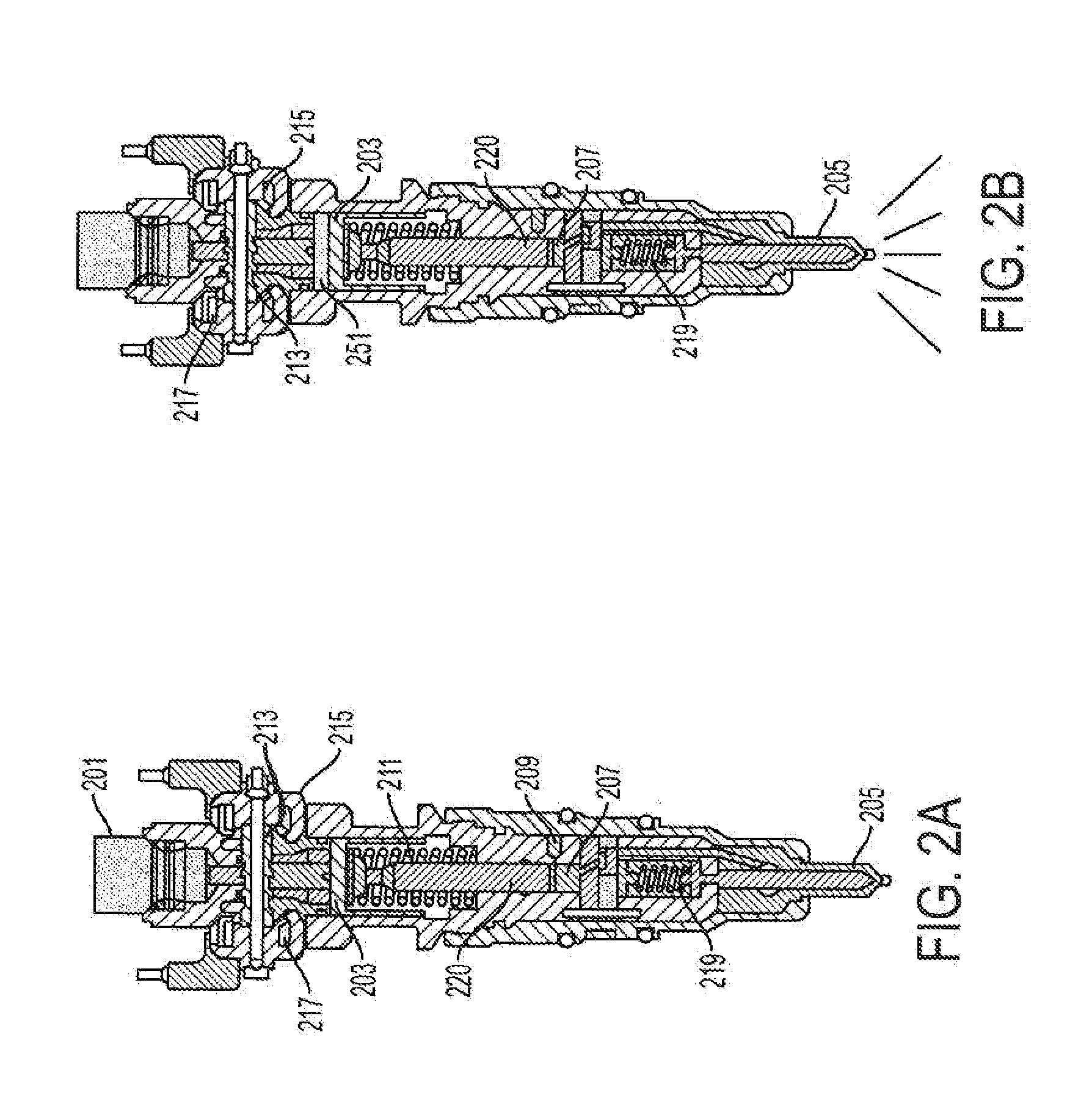
[0002]Internal combustion engine performance and emissions can be improved by injecting fuel into cylinders. One type of fuel injector acts as an intensifier and increases fuel pressure above the pressure that is delivered by a downstream fuel pump. U.S. Pat. No. 5,954,030 describes one such injector. This patent presents a system for operating a fuel injector that is capable of injecting fuel directly into a cylinder of an internal combustion engine. The system controls fuel flow by adjusting the position of a spool valve. The spool valve position is changed by flowing current to a charge coil or a discharge coil. When current is allowed to flow to the charge coil, the spool valve is attracted to the charge coil and fuel is allowed to enter an intensifier chamber. When current is allowed to flow to the discharge coil, the spool valve is attracted to the discharge coil and fuel is compressed in the intensifier chamber and released to the cylinder at a higher pressure. The charge and discharge coils position the spool valve so that the working fluid (i.e., pressurized oil), acts on the intensifier piston to compress the fuel in the intensifier chamber or to return the intensifier piston so that lower pressure fuel may enter the intensifier chamber. The pressurized oil acts on the intensifier piston, which acts on a smaller piston, and multiplies the force that is pressurizing the fuel. However, at cold operating temperatures, frictional losses in the injector increase, thereby increasing the power necessary to operate the injector. Further, the increased mechanical viscous friction changes the valve response and can also increase the complexity of controlling the valves under varying operating conditions.
[0004]The procedure for heating fuel injectors may be improved by sequentially heating a group of injectors so that instantaneous electrical current is reduced. An injector may be heated by current supplied from a power source, such as a battery or alternator. Heating the injector can improve injector performance and response, thereby improving air-fuel control and lowering engine starting emissions. However, if injectors of a multiple cylinder engine are simultaneously heated by a limited number of current sources, then the current capacity of the current sources may have to be increased. In addition, the size of conductors between the current source and the injectors may also have to be increased so that the conductor can carry the additional current. The present system and method reduces the amount of current used to heat the injectors at any one time by heating the injectors in a one-after-the-other sequence. In this way, only the current used to heat a single fuel injector is used at any one time. In other embodiments, current may flow into a first injector for a short period while current begins to flow to in a second fuel injector. When current flowing to the first injector is stopped some of the free wheel current is transferred to the second injector, thereby reducing the system current requirements. In still another embodiment, injector groups of injectors may be sequentially heated so that injector heating time can be reduced while still lowering the instantaneous current used to heat the injectors of an engine. For example, an eight cylinder engine having eight fuel injectors can have four groups of two injectors that are sequentially heated. Thus, in this example, the injector heating time can be reduced by half while the injector heating current is doubled. Consequently, injector heating current can be weighed against injector heating time, thereby allowing system designers to select a compromise between electrical current requirements and injector heating time.
[0005]The present description may provide several advantages. Namely, fuel injectors may be heated in a way that reduces the instantaneous current requirements of a vehicle's electrical system while still reducing meniscus forces. Further, the system cost may be reduced because the higher capacity components may not be required. For example, the wire gauge between the power source and the injectors may be made lighter without affecting the system function or performance. In addition, the engine air-fuel control may be improved because engine emissions may be improved because there may be fewer circumstances where the engine air-fuel ratio is leaner than desired when fuel injectors are heated.

Problems solved by technology

However, at cold operating temperatures, frictional losses in the injector increase, thereby increasing the power necessary to operate the injector.
Further, the increased mechanical viscous friction changes the valve response and can also increase the complexity of controlling the valves under varying operating conditions.
However, if injectors of a multiple cylinder engine are simultaneously heated by a limited number of current sources, then the current capacity of the current sources may have to be increased.

Method used


Image

  • System and method for reducing power consumption when heating a fuel injector
  • System and method for reducing power consumption when heating a fuel injector
  • System and method for reducing power consumption when heating a fuel injector

Examples


Embodiment Construction

[0019]The present description anticipates a variety of applications wherein the present description can be used to advantage. For example, the present description may be used to improve operation of two position spool valves, three position spool valves, pintle needle valves, valves that are operated by single or multiple coils, poppet valves, ball valves, gate valves, piezoelectric devices, and butterfly valves. Further, the present description may be applied in a variety of fields including automobiles, aircraft, process industries, mining, and manufacturing. Accordingly, this description is not intended to limit the scope or breadth of the claims or disclosure.

[0020]Electrically operable mechanical valves vary in design and construction. They may also be operated over a wide range of environmental conditions. Further, it may be desirable to provide different types of heating for different valve designs and / or during different operating conditions. A partial but not limiting list ...


PUM


Abstract

A system and method to reduce the instantaneous power consumption during heating of a fuel injector is described. The system is capable of heating the fuel injectors of an engine at different times.

Description

FIELD [0001]The present description relates to a system and method for improving the performance of fuel injectors. The method can improve fuel control over a range of operating conditions.BACKGROUND AND SUMMARY [0002]Internal combustion engine performance and emissions can be improved by injecting fuel into cylinders. One type of fuel injector acts as an intensifier and increases fuel pressure above the pressure that is delivered by a downstream fuel pump. U.S. Pat. No. 5,954,030 describes one such injector. This patent presents a system for operating a fuel injector that is capable of injecting fuel directly into a cylinder of an internal combustion engine. The system controls fuel flow by adjusting the position of a spool valve. The spool valve position is changed by flowing current to a charge coil or a discharge coil. When current is allowed to flow to the charge coil, the spool valve is attracted to the charge coil and fuel is allowed to enter an intensifier chamber. When curr...

Claims


Application Information

Patent Timeline
IPC IPC(8): F02M53/06F02M61/04
CPCF02M53/06
Inventor STEPHAN, CRAIGWINELAND, RICHARDELIE, LARRYMARANVILLE, CLAYGALE, ALLAN
Owner FORD GLOBAL TECH LLC
Learn More