High performance low volume inductor and method of making same

Active Publication Date: 2008-05-29
GENERAL ELECTRIC CO
View PDF5 Cites 49 Cited by
  • Summary
  • Abstract
  • Description
  • Claims
  • Application Information

AI Technical Summary

Benefits of technology

[0008]The present invention provides an improved inductor for an RF electrical circuit that overcomes the aforementioned drawbacks. An inductor constructed with carbon nanotubes benefits from an increased Q factor at a reduced area and volume.

Problems solved by technology

However, existing inductor constructions are often too large, in area and volume, to incorporate into high channel count of small designs where miniaturization is desired.
As such, loss of inductive quality occurs when resistance of the electrical conductor is increased or when inductance, L, is decreased.
Reduced Q factor thereby causes reduced performance of an electrical circuit, and in particular, an electrical circuit in a RF receiver coil of a MR system.
Additionally, use of a ferromagnetic core material in an inductor is not compatible with use in an MR system.

Method used


Image

  • High performance low volume inductor and method of making same
  • High performance low volume inductor and method of making same
  • High performance low volume inductor and method of making same

Examples


Embodiment Construction

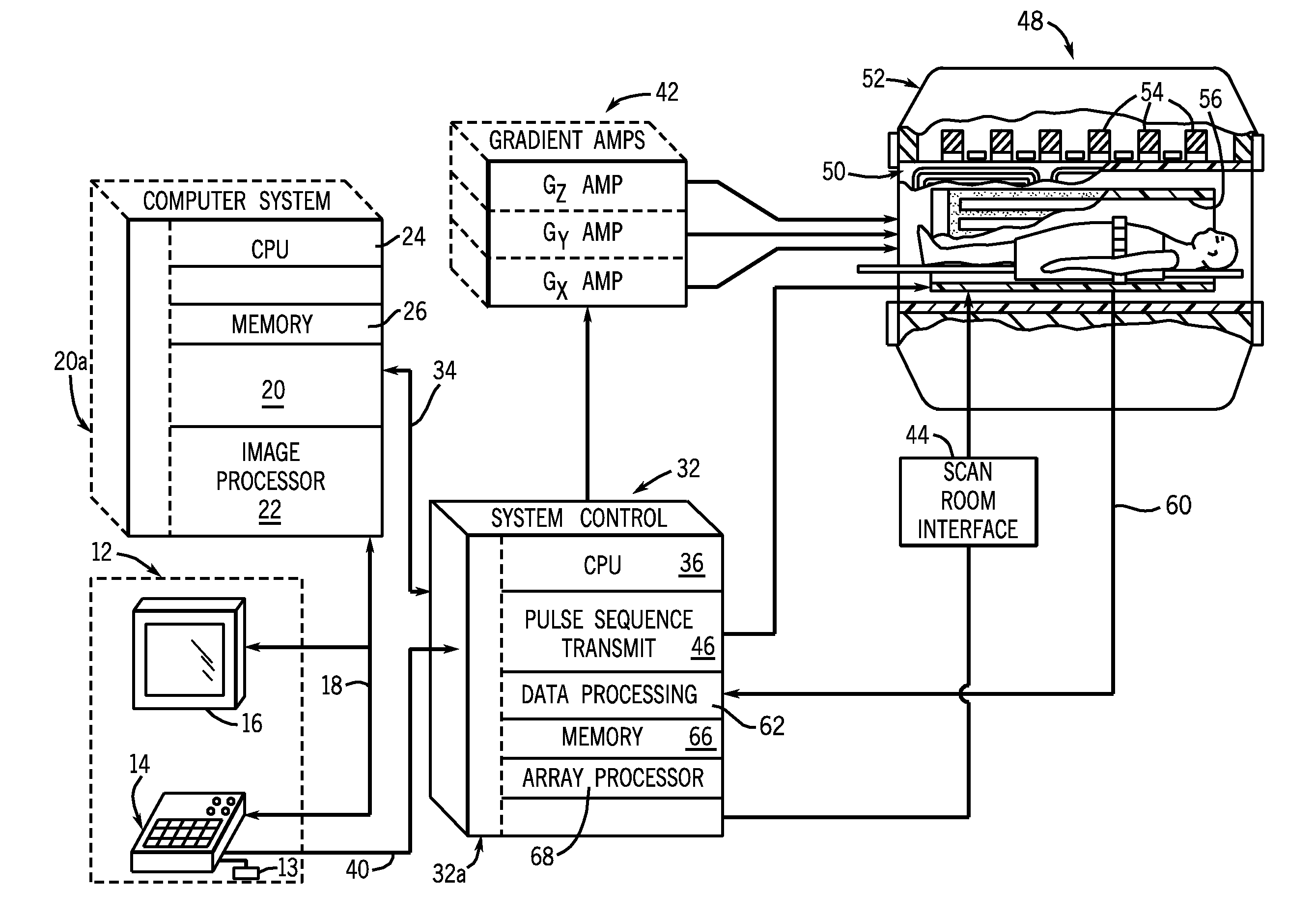
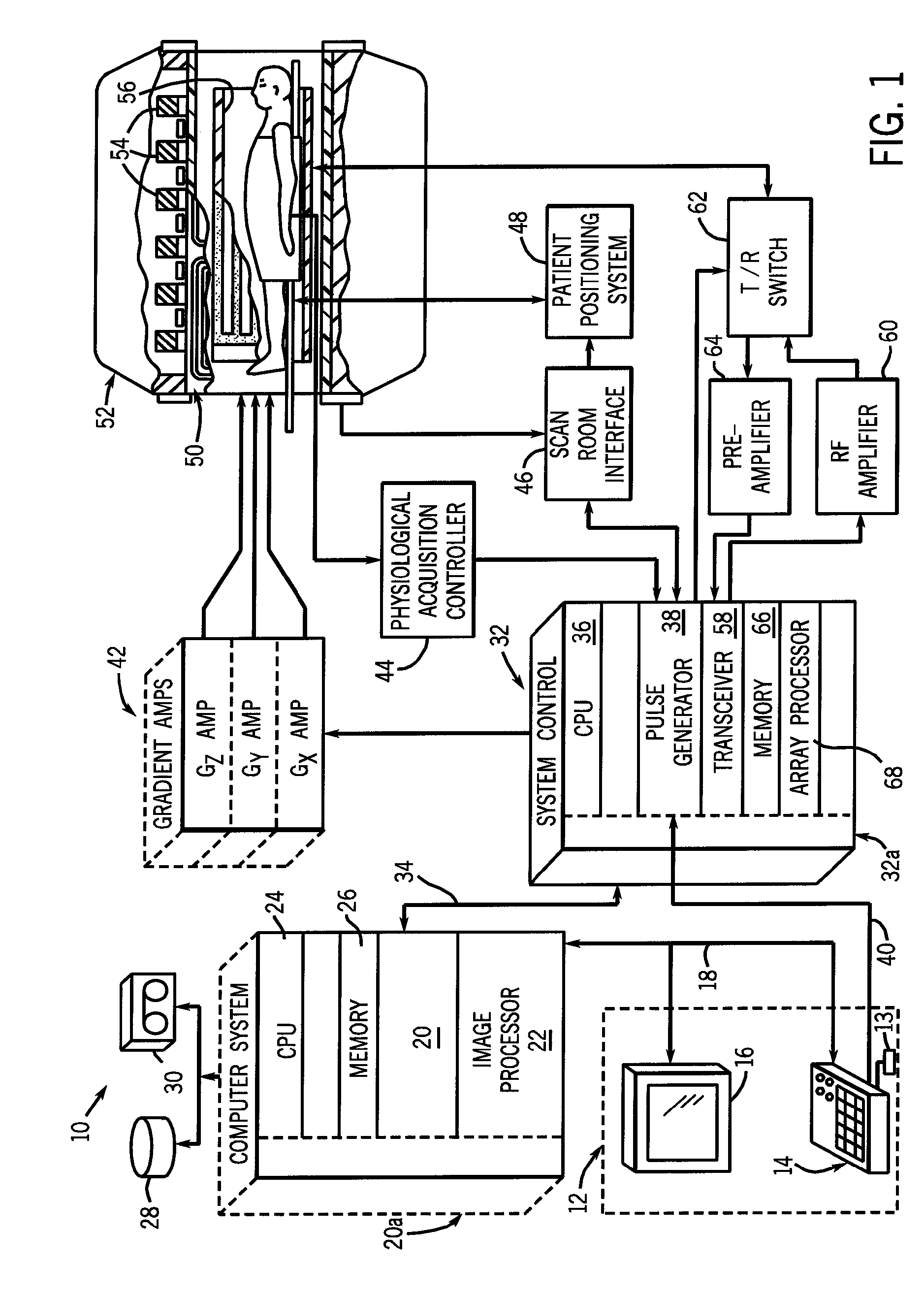
[0025]Referring to FIG. 1, the major components of a preferred magnetic resonance imaging (MRI) system 10 incorporating the present invention are shown. The operation of the system is controlled from an operator console 12 which includes a keyboard or other input device 13, a control panel 14, and a display screen 16. The console 12 communicates through a link 18 with a separate computer system 20 that enables an operator to control the production and display of images on the display screen 16. The computer system 20 includes a number of modules which communicate with each other through a backplane 20a. These include an image processor module 22, a CPU module 24 and a memory module 26, known in the art as a frame buffer for storing image data arrays. The computer system 20 is linked to disk storage 28 and removable storage 30 for storage of image data and programs, and communicates with a separate system control 32 through a high speed serial link 34. The input device 13 can include...


PUM

PropertyMeasurementUnit
Magnetic fieldaaaaaaaaaa
Structureaaaaaaaaaa
Magnetic fluxaaaaaaaaaa

Abstract

An inductor includes an electrical conductor wound in a magnetic flux concentrating pattern, the electrical conductor comprises a plurality of carbon nanotubes that are substantially aligned with an axis along a center of the electrical conductor.

Description

BACKGROUND OF THE INVENTION[0001]The present invention relates generally to inductors, and, more specifically, to a high performance inductor incorporating carbon nanotubes in its construction.[0002]When a substance such as human tissue is subjected to a uniform magnetic field (polarizing field B0), the individual magnetic moments of the spins in the tissue attempt to align with this polarizing field, but process about it, in random order, at their characteristic Larmor frequency. If the substance, or tissue, is subjected to a magnetic field (excitation field B1) which is in the x-y plane and which is near the Larmor frequency, the net aligned moment, or “longitudinal magnetization”, MZ, may be rotated, or “tipped”, into the x-y plane to produce a net transverse magnetic moment Mt. A signal is emitted by the excited spins after the excitation signal B1 is terminated and this signal may be received and processed to form an image.[0003]When utilizing these signals to produce images, m...

Claims


Application Information

Patent Timeline
IPC IPC(8): G01R33/34H01F5/00H01F41/06H01F27/28
CPCG01R33/34007G01R33/34046G01R33/341Y10T29/49071H01F7/202H01F27/2823H01F27/2847H01F5/00
Inventor BURDICK, WILLIAM E.LEE, JI-UNGDE ROOIJ, MICHAEL A.
Owner GENERAL ELECTRIC CO
Why Eureka
Try Eureka