
Device for producing high speed air projectiles or pulses

a high-speed air and projectile technology, applied in the field of air cannons, can solve problems such as air pressure, achieve the effects of increasing the volume of air that is displaced, fast response, and increasing electrical power handling

Inactive Publication Date: 2008-05-29
DISNEY ENTERPRISES INC
View PDF32 Cites 9 Cited by
  • Summary
  • Abstract
  • Description
  • Claims
  • Application Information

AI Technical Summary

Benefits of technology

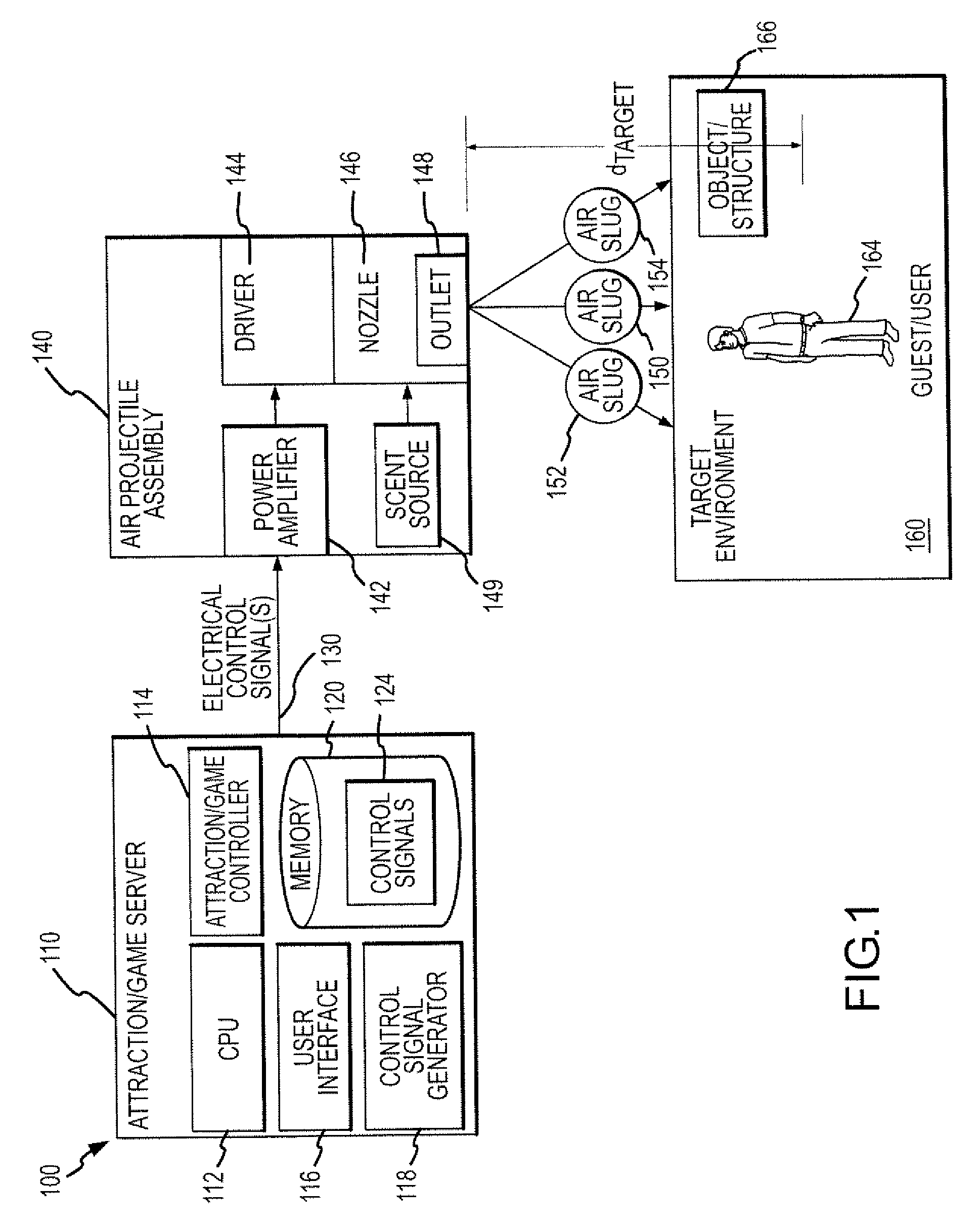
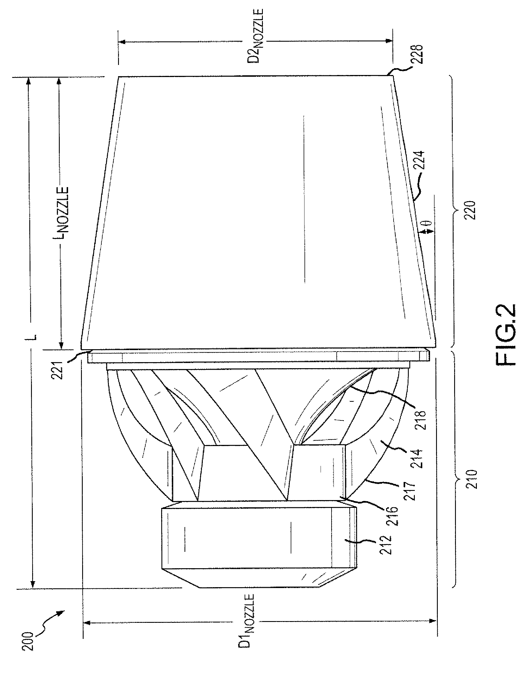
[0008]The present invention addresses the above problems by providing an air projectile assembly that provides a very fast response to a control signal to shoot or discharge a high speed volume or slug of air. In one embodiment, the invention combines a driver of an audio speaker (which may be also known as a loudspeaker, a voice coil loudspeaker, or the like) with a converging nozzle. For example, the driver may be a large diameter woofer or voice coil device for a loudspeaker. The converging nozzle is sealed to the loudspeaker driver and includes a planar end piece or muzzle at the distal end that has a smaller outlet or opening (e.g., less than about 6 inches in many applications). A driver is selected with a large throw such as an excursion of 1 to 3 inches or more of its flexible diaphragm or cone (as typically measured peak to peak or, in some cases, rest to peak). In some embodiments, two or more drivers or loudspeakers are mounted on a manifold such that their excursions and air displacement may be combined with concurrent firing (or for firing in series). The multiple drivers may feed a common exit to increase the electrical power handling or increase the volume of air that is displaced. A control signal is selectively provided to the driver to cause the driver to move through at least its forward throw (e.g., toward the nozzle or away from the driver itself). The control signal may have a short duration or cycle to cause the displacement of the driver's cone to occur rapidly such as less than about 100 millisecond and typically less than 20 milliseconds. This causes a rapid displacement of air next to the cone within the nozzle's bore or chamber, which results in pressurization of the air in the nozzle bore and a projectile to be expelled or shot out the opening in the muzzle or distal end of the converging nozzle.
[0009]Tests show that a slug or projectile of air can be rapidly transmitted across a distance of 10 to 30 feet (e.g., in less than about 1 second) by using a high-power woofer (e.g., a woofer rated at 500 to 1000 Watts RMS) for the driver that has a diaphragm diameter of about 13 inches along with a 13-inch long nozzle that converges at a slope of 5 to 10 degrees and has a muzzle with a 1 to 3-inch diameter round hole or outlet. The assemblies of the invention are much quieter and less bulky than existing industrial air cannons, are less expensive to produce, and require little or no maintenance. Further, the use of all or portions of audio signals or waves (e.g., such as may be produced with standard audio tone or wave generation software and the like) allows easy control of the driver and the production of differing projectiles as the driver responds differently based on the control signals, which allows projectiles of differing size and speed to be transmitted simply by sending differing control signals to the driver. There are many possible driving electrical waveforms. The wave or waveform can be varied to alter the duration, velocity, and / or force of the ejected air pulse or projectile. One method for operating the driver is to ramp the waveform from zero to maximum to drive the voice coil of the driver to one mechanical limit and then to reverse the polarity to suddenly propel the cone or diaphragm to the other mechanical limit of the loudspeaker. This technique generally displaces the maximum or substantially the maximum volume of air for which the particular loudspeaker is capable based on its design.

Problems solved by technology

This causes a rapid displacement of air next to the cone within the nozzle's bore or chamber, which results in pressurization of the air in the nozzle bore and a projectile to be expelled or shot out the opening in the muzzle or distal end of the converging nozzle.

Method used


Image

  • Device for producing high speed air projectiles or pulses
  • Device for producing high speed air projectiles or pulses
  • Device for producing high speed air projectiles or pulses

Examples


Embodiment Construction

[0018]Briefly, the present invention is directed to air projectile devices that utilize a driver such as a bass audio speaker or woofer combined with a converging nozzle. The driver is triggered or controlled by a pulse such as an audio or other electrical signal that is typically amplified so as to cause a relatively large flexible membrane or cone of the driver to rapidly move or travel through its throw (e.g., at least the forward or outward portion of the driver's excursion or throw). The driver membrane or cone is provided proximate to the larger end of the nozzle and displaces a volume of air in the bore or chamber of the nozzle that is forced through the outlet in the smaller end of the nozzle toward a target. The nozzle acts to concentrate the air into a projectile or slug that is expelled at high velocity out the small diameter outlet (e.g., less than about 5 inches such as about 2 inches diameter circular hole) in the nozzle's muzzle, which may planar or, in some cases, fr...


PUM


Abstract

An assembly for producing air projectiles. The assembly includes a driver with an attached converging nozzle. The driver includes a flexible diaphragm and is responsive to an electrical control signal to displace the flexible diaphragm from a first position to a second position. In one embodiment, the driver is an audio speaker driver such as a woofer and the diaphragm is a speaker cone or diaphragm. The nozzle has an inner bore or chamber that converges from a first size at a first end proximate to the driver to a second, smaller size at a second distal end. The second end of the nozzle may include a planar muzzle extending perpendicular to a central axis of the bore and including an outlet smaller than the diaphragm diameter. The driver has a rapid response to control signals such as less than about 20 milliseconds to produce a projectile at the muzzle.

Description

BACKGROUND OF THE INVENTION[0001]1. Field of the Invention[0002]The present invention relates, in general, to air cannons and other devices that operate to generate air rings, air and smoke vortices, and puffs of air, and, more particularly, to a device, and method of operating such a device, that quietly produces air projectiles or pulses that travel at relatively high speeds while generally retaining their shape, e.g., a projectile, slug, or pulse rather than rapidly dispersing.[0003]2. Relevant Background[0004]Air “cannons” are commonly used to prevent buildups of material and to improve material flow in industrial settings. Generally, these industrial-use cannons use an accumulator or tank to store a quantity of pressurized air from a compressor or other source. A large-flow, fast-acting valve is then used to selectively release a quantity of the air through a nozzle or other outlet. These air cannons provide an effective technology for use in removing possible bottlenecks in pi...

Claims


Application Information

Patent Timeline
IPC IPC(8): F41B11/00
CPCF41H13/00F41B11/00
Inventor WILDER, TODDKADAR, ISTVAN B.
Owner DISNEY ENTERPRISES INC
Learn More