
Rotary actuator

a technology of rotary actuators and piston rods, which is applied in the direction of reciprocating piston engines, steam engine plants, positive displacement engines, etc., can solve the problem that the actuators do not provide a piston rod, and achieve the effect of preventing the diaphragm from twisting

Inactive Publication Date: 2008-05-29
THERMOTION ACQUISITION
View PDF8 Cites 13 Cited by
  • Summary
  • Abstract
  • Description
  • Claims
  • Application Information

AI Technical Summary

Benefits of technology

[0008]Elements may be included in the actuator to avoid the transmission of torsional forces from the piston to other elements of the actuator. Such an element, referred to here as a second piston may be interposed between the first or principal piston and the diaphragm, which moves upon expansion of the working fluid. This bearing prevents the twisting of the diaphragm. A thrust bearing may be interposed between the spring and the one of the housing and the first piston to prevent the transmission of torsion to the spring.

Problems solved by technology

Those actuators do not provide a piston rod for driving an external mechanical device with linear motion and / or rotary motion in response to electrical power applied to the actuator.

Method used


Image

  • Rotary actuator
  • Rotary actuator
  • Rotary actuator

Examples


Embodiment Construction

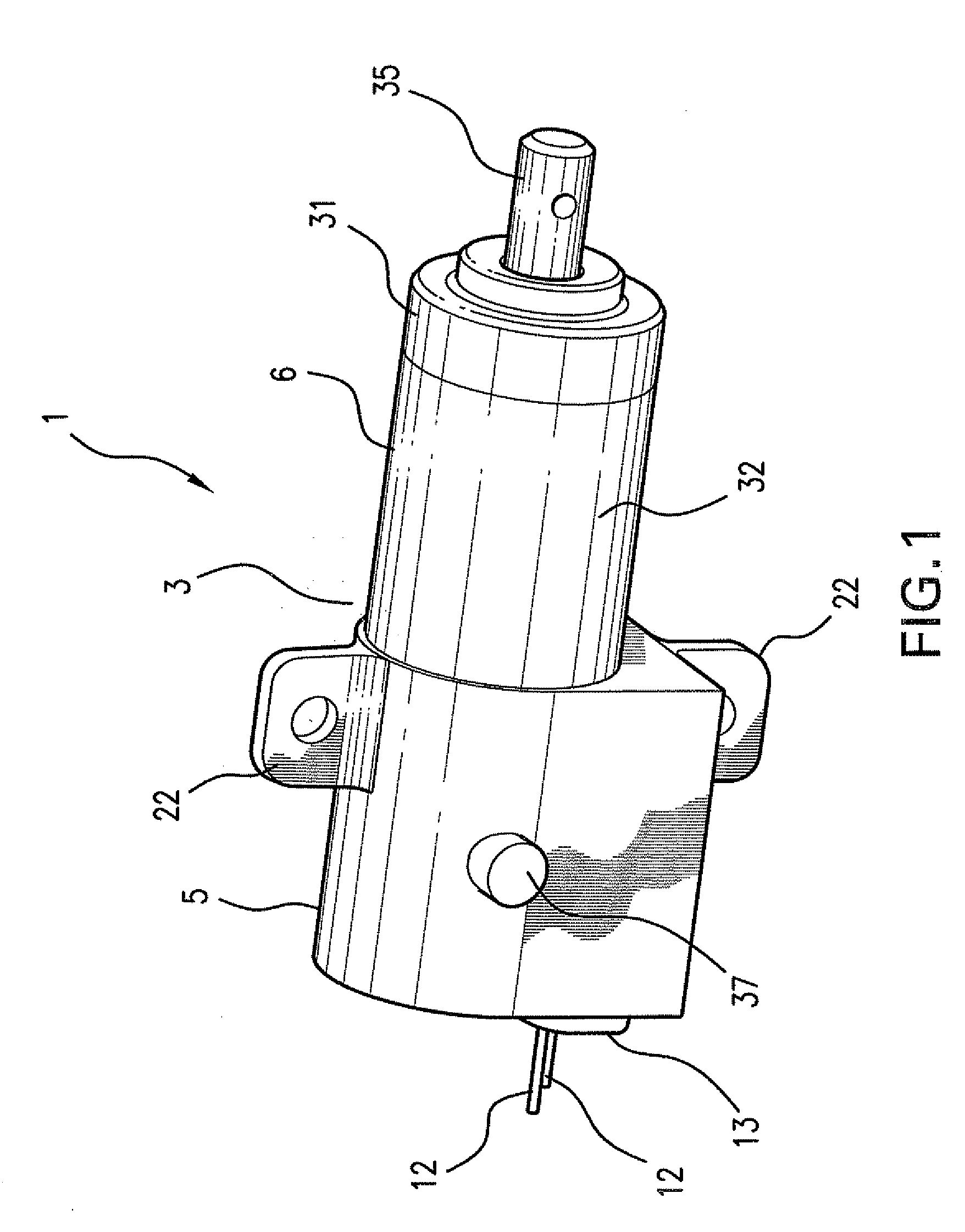
[0015]FIGS. 1-5 show, in different views, an embodiment of an actuator 1 according to the invention. The actuator 1 includes a housing 3 including a rear housing part 5 and a front housing part 6. The front and rear housing parts 5 and 6 are preferably molded plastic parts that are bonded together, for example by ultrasonic welding. Of course, those parts could be metallic and joined by any conventional process. When the housing parts are made of plastic, the plastic must be able to withstand the maximum temperature of the heater and the working fluid.

[0016]The rear housing part 5 includes a chamber 10 (see FIGS. 3 and 4) that contains the working fluid, frequently a fluorocarbon. The chamber also houses an electrical heater 11, shown in the form of a disk, with electrical leads 12 that pass through a plug 13 that closes a hole in the rear housing part 5. Preferably, the plug 13 is plastic and is ultrasonically welded to the surfaces of the rear housing part that define the opening ...


PUM


Abstract

An electrothermal actuator producing linear and / or rotational movement includes a housing having a longitudinal axis. A chamber within the housing contains a working fluid that changes phase upon heating. A piston is slidably disposed within the housing and movable along the longitudinal axis between first and second positions. A spring biases the piston toward the first position. The piston slides from the first position to the second position in response to heating of the working fluid. The piston includes a piston rod extending along the longitudinal axis and protruding from the housing. The housing includes helical grooves on an interior surface and the piston includes partially spherical recesses. Balls captured between the grooves and recesses produce rotation of the piston and piston rod when the piston moves between the first and second positions.

Description

FIELD OF THE INVENTION[0001]The present invention relates to actuators in which rotary and / or linear motion is produced in response to electrical power. The invention particularly relates to actuators having a piston rod that rotates and reciprocates during operation of the actuator.BACKGROUND OF THE INVENTION[0002]Actuators producing mechanical movement of an object in response to the application of electrical power are well known. Among the types of actuators that respond to the application of electrical power to produce mechanical motion are electrothermal actuators. Examples of such actuators are described in U.S. Pat. Nos. 4,759,189, 4,887,429, and 5,203,171, which are incorporated by reference. Within these electrothermal actuators, a closed chamber contains a working fluid. The working fluid is mostly a liquid at ambient temperature and changes phase to become a gas, when heated. That gas phase of the working fluid expands upon continued heating, increasing internal pressure ...

Claims


Application Information

Patent Timeline
IPC IPC(8): F03G7/06
CPCF03G7/06
Inventor SAFRAN, LESDOUGLASS, STEPHEN L.
Owner THERMOTION ACQUISITION
Learn More