Eureka AIR delivers breakthrough ideas for toughest innovation challenges, trusted by R&D personnel around the world.

Tracking method

a tracking method and navigation technology, applied in direction finders, navigation instruments, instruments using radio waves, etc., can solve the problems of imbalance of energy within different beams, insufficient accuracy for other tasks, and imbalance of energy

Active Publication Date: 2008-05-22
STATE OF ISRAEL MINIST OF AGRI & RURAL DEV AGRI RES ORG (A R O) (VOLCANI CENT)
View PDF14 Cites 108 Cited by
  • Summary
  • Abstract
  • Description
  • Claims
  • Application Information

AI Technical Summary

Problems solved by technology

While this is sufficiently accurate for some tasks such as locating the target, it is not accurate enough for other tasks.
However, when the target is off the tracking axis an imbalance of energy occurs within the different beams.
This imbalance of energy is used to generate an error signal that drives the servo-control system.
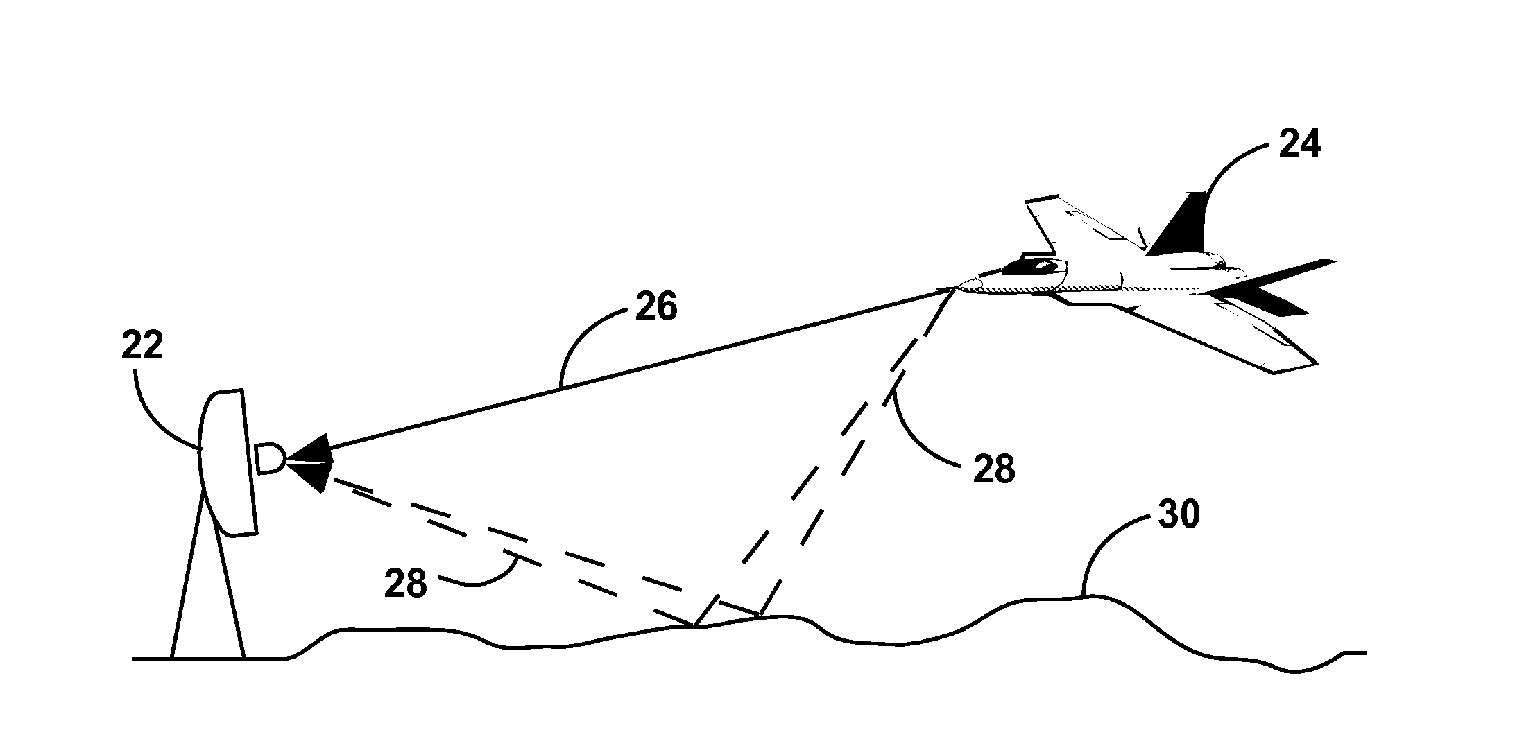
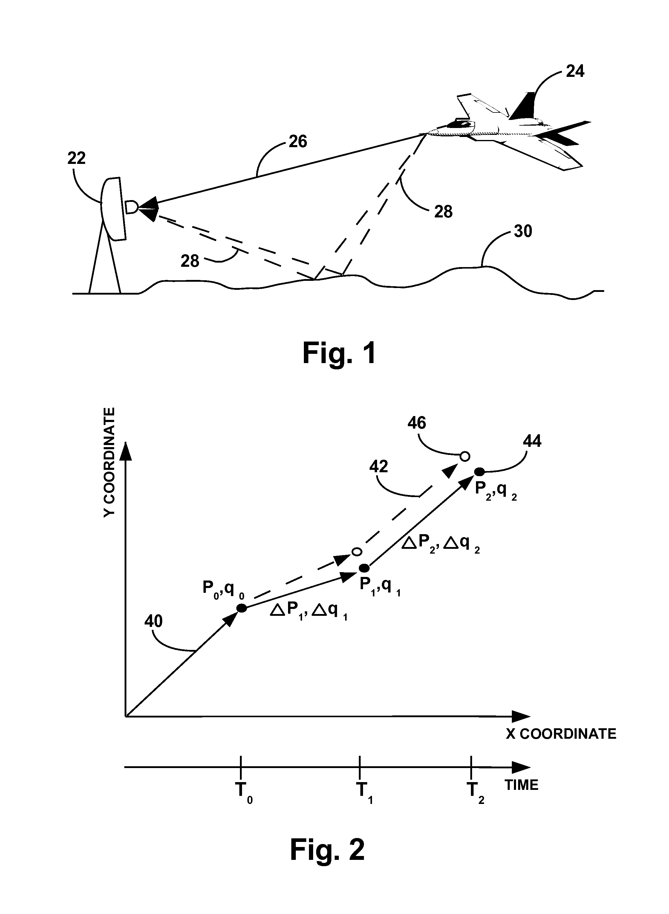
Measurement of the return EM reference from a moving platform is not accurate and is sensitive to return EM intensity variations (e.g. as a result of airplane maneuvers).
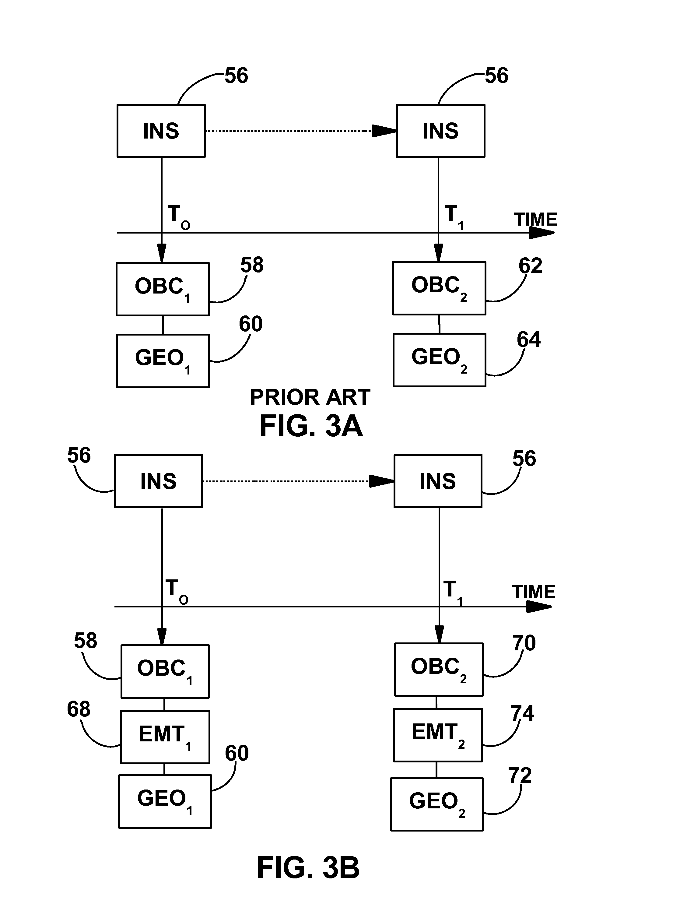
INS suffers from integration drift, as small errors in measurement are integrated into progressively larger errors in velocity and especially position.
This is a problem that is inherent in every open loop control system.
The MP tracking errors such as position, orientation, velocity and acceleration in both methods cause degradations in tracking performance.
Such degradations are noticeable, for example, when using a narrow beam antenna to track an MP, in such a case an accurate tracking system is needed to pin-point an MP.
As the tracking error increases (i.e. the antenna axis is shifted with respect to the line of sight) the signal power decreases proportionally to the tracking error (within the limits of the main lobe).

Method used


Image

  • Tracking method
  • Tracking method
  • Tracking method

Examples


example 1

Kalman Filter for State Estimation

[0055]The standard Kalman filter cannot be used directly with the equations given above, because the equations are nonlinear, in particular motor encoder measurement equations.

[0056]A possible solution is to use an adaptive filter such as the nonlinear Kalman filter, extended Kalman filter, particle filter or scented filter. One such technique is disclosed in M. Nørgaard, N. K. Poulsen, and O. Ravn, “Advances in Derivative Free State Estimation for Nonlinear Systems”, Technical report IMM-REP-1998-15, Technical University of Denmark, 2000, the contents of which are incorporated herein by reference.

example 2

Explanation of FIG. 8, Kalman Filter Block Diagram in the Context of the Present Invention

[0057]An example of a Kalman filter implementation in the context of the present invention is described schematically in FIG. 8 which reference is now made. A Kalman filter initially receives as an input prior estimation of EMT and INS state data 150 prior EMT and INS covariance 152 and New EMT and INS measurements 154. The state 156 and covariance 158 predictions are than updated using a dynamic mathematical model. Kalman gain is then calculated160 and the NMPS is updated 162 using the gain and the difference between predicted state 156 and newly measured state 154. New azimuth and elevation parameters 164 as calculated from the updated state are utilized in order to send to the antenna a tracking command. The covariance is updated 160 as a preparation to the next Kalman procedure.

[0058]Number and Deployment of Tracking Units

[0059]In accordance with the present invention, the MP state data can...


PUM


Abstract

A method for tracking a moving platform (MP) wherein the MP uses an on-board navigation system (NS). Data provided by the navigation system on board the moving platform (MP) is merged with data obtained using a tracking system that tracks the MP from another location. A typical navigation system on board the moving platforms is an inertial navigation system (INS). State data of one or more MP is sent to a processing facility and state data of one or more electromagnetic tracking (EMT) is collected by one or more processing facility. The collected states data from the sources are processed, using the one or more processing facilities for calculating tracking data are used to direct one or more antennas for MP tracking. The state data from one or more MP's are sent using a communications channel.

Description

FIELD OF THE INVENTION[0001]The present invention is in the field of inertial navigation. More specifically the invention is regarding combination of information from several sources to improve the accuracy of tracking a platform bearing a navigation system.BACKGROUND OF THE INVENTION[0002]Inertial and electromagnetic tracking are the two main methods of tracking mobile platforms (MP) such as airplanes, missiles, boats and cars. An electromagnetic tracking system (EMT) is typically based on estimating the direction of the maximum electromagnetic intensity at the receiver. Step track, conical scan and monopulse are examples of EMT methods.[0003]An antenna typically has a beam width ranging from a fraction of a degree to several degrees. While this is sufficiently accurate for some tasks such as locating the target, it is not accurate enough for other tasks. In step tracking which is also referred to as hill climbing, the signal location is assumed known within the uncertainty of the ...

Claims


Application Information

Patent Timeline
Patent Type & Authority Applications(United States)
IPC IPC(8): G01C21/00G01C21/02H01Q3/00
CPCG01C21/165G01S7/003H01Q3/10G01S13/723G01S13/86G01S7/2955
Inventor ROSENFELD, DANIELSALAMA, OFER
Owner STATE OF ISRAEL MINIST OF AGRI & RURAL DEV AGRI RES ORG (A R O) (VOLCANI CENT)
Why Eureka
Eureka Blog
Learn More