
Dual voltage battery with separate terminals

Inactive Publication Date: 2008-05-22
BRENNFOERDER DUDLEE
View PDF2 Cites 23 Cited by
  • Summary
  • Abstract
  • Description
  • Claims
  • Application Information

AI Technical Summary

Benefits of technology

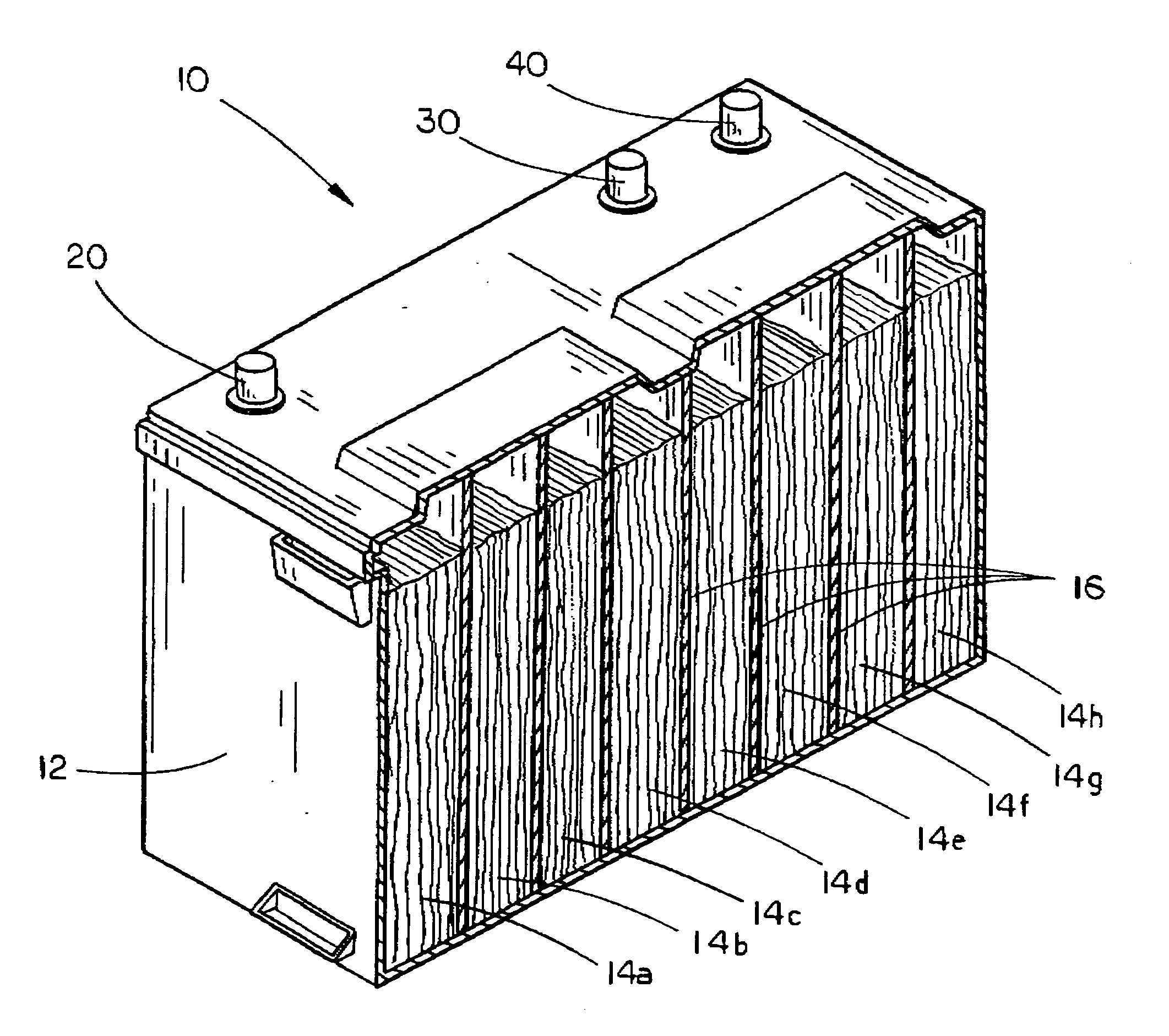
[0013]The present invention thus provides numerous advantages over the prior art. For example, because the present invention includes three separate battery terminals, two of which are positive for different voltages, separate electrical systems may be connected to the battery and can remain connected regardless of which system is drawing power from the battery, thus eliminating the need for disconnecting and reconnecting the separate electrical system devices. Furthermore, as the present invention eliminates the need for a switching device which is usable to switch between 12 volt and 16 volt output, because the battery outputs both voltages simultaneously, the present invention can be used with electrical systems requiring different voltages yet which the user desires to use simultaneously. Finally, because the present invention utilizes existing technology in a new functional configuration, it may be quickly and easily constructed and implemented, which renders the present invention a substantial improvement over the prior art.

Problems solved by technology

Operating below this voltage level can cause ignition problems such as a high-speed miss, or problems with audio equipment including amp failure and component malfunction.
Reduced voltage will also negatively affect the starter's ability to spin the motor.
However, many other electrical accessories on the vehicle cannot function with delivery of 16 volts, instead requiring a 12 volt feed to prevent damage to the accessory, ignition head units, etc.
While this design may be adequate for certain uses, in situations where simultaneous output of both 12 volt and 16 volt current is demanded, these devices fall short of solving the existing problems.

Method used


Image

  • Dual voltage battery with separate terminals
  • Dual voltage battery with separate terminals
  • Dual voltage battery with separate terminals

Examples


Embodiment Construction

[0016]The dual voltage output vehicle battery 10 of the present invention is shown best in FIGS. 1 and 2 as including a battery case 12 which is preferably constructed of a reinforced, gusseted, high impact polyethylene case material to ensure that the battery 10 is highly resistant to impact and vibration damage and further that the case material reinforces the unit's rigidity. Mounted on the outer top wall of the battery case 12 are three battery terminals, the first being a standard ground or negative terminal 20, the second terminal (shown in yellow in FIG. 1) being the 12-volt positive terminal 30 and the third terminal (shown in red in FIG. 1) being the 16-volt positive terminal 40. The terminals 20, 30 and 40 may be of any appropriate design, and it has been found that the terminal design is not critical to the functionality of the present invention regarding voltage and amperage output, so long as the terminals are conductive and relatively easy and secure to mount the elect...


PUM


Abstract

The present invention provides a dual voltage battery with separate terminals which includes an outer case and a plurality of current-producing battery cells mounted within the outer case, the plurality of battery cells being connected in serial connection. A negative ground terminal is mounted on the outer case, and a first positive terminal is mounted on the outer case and is connected to at least some of the battery cells via the serial connection to produce 12 volt current output therefrom. A second positive terminal is mounted on the outer case and is connected to all of the battery cells via the serial connection to produce 16 volt current output therefrom. Finally, the first and second positive terminals are separate from one another such that the dual voltage battery outputs 12 volt and 16 volt current simultaneously via the first and second positive terminals.

Description

CROSS-REFERENCE TO RELATED PATENTS[0001]This application claims priority based on a provisional patent, specifically on the Provisional Patent Application Ser. No. 60 / 860,833 filed Nov. 22, 2007.BACKGROUND OF THE INVENTION[0002]1. Technical Field[0003]The present invention is directed to vehicle batteries and, more particularly, to a dual voltage output vehicle battery which includes eight battery cells connected in serial connection, a negative terminal, a first positive terminal connected to six of the battery cells in series to produce 12 volt output, a second positive terminal connected to all eight of the battery cells in series to produce 16 volt output, the first and second positive terminals being separate from one another such that the dual voltage output vehicle battery is connectable to two separate electrical systems in the same vehicle, thus powering high performance vehicle electrical accessories as well as standard vehicle electrical accessories.[0004]2. Description o...

Claims


Application Information

Patent Timeline
IPC IPC(8): H01M2/24H01M50/529H01M50/552
CPCH01M2/24H01M6/42H01M2/30H01M50/529H01M50/552
Inventor BRENNFOERDER, DUDLEE
Owner BRENNFOERDER DUDLEE
Learn More