
Automatic circuit and method for temperature compensation of oscillator frequency variation over temperature for a real time clock chip

a real-time clock and oscillator technology, applied in the field of electronic devices, can solve the problems of large chip area, large chip area, and significant power consumption, and achieve the effect of low power operation

Active Publication Date: 2008-05-22
INTERSIL INC
View PDF7 Cites 11 Cited by
  • Summary
  • Abstract
  • Description
  • Claims
  • Application Information

AI Technical Summary

Benefits of technology

"The patent text is submitted to comply with a regulation that requires an abstract that explains the technical disclosure. The abstract is not meant to limit the scope or meaning of the claims. The technical effect of this patent is to provide a way to quickly understand the nature of the invention without having to read through all the details."

Problems solved by technology

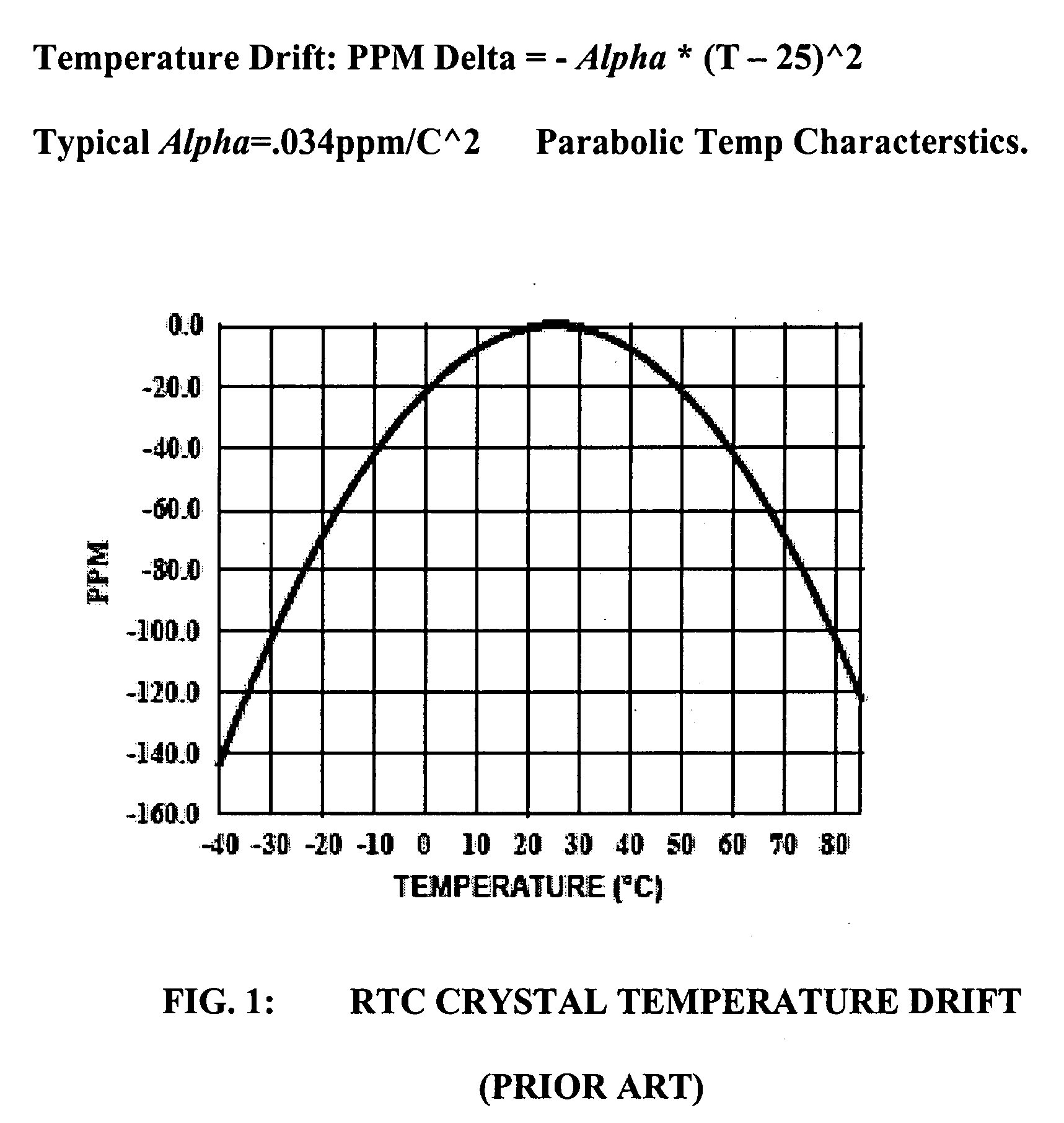
For precision applications requiring better than +5 ppm precision over a normal operating temperature range, such a non-linear frequency trim arrangement generally cannot meet the requirement.
Using known methods, this would require nonlinear digital signal processing which can be complex, and also generally requires a large chip area and significant power consumption.

Method used


Image

  • Automatic circuit and method for temperature compensation of oscillator frequency variation over temperature for a real time clock chip
  • Automatic circuit and method for temperature compensation of oscillator frequency variation over temperature for a real time clock chip
  • Automatic circuit and method for temperature compensation of oscillator frequency variation over temperature for a real time clock chip

Examples


Embodiment Construction

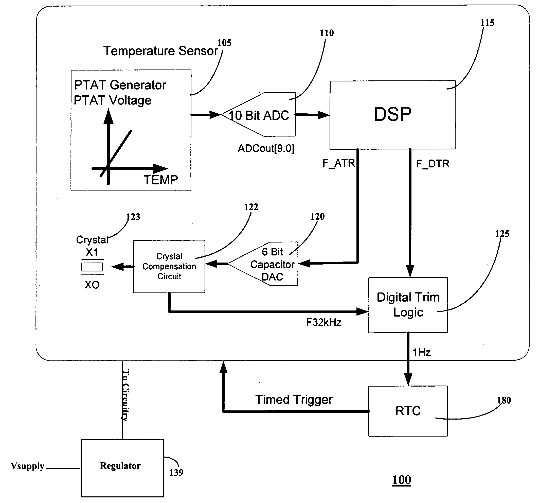
[0032]An automatic temperature compensated real time clock (RTC) chip comprises a clock portion including a crystal oscillator block comprising crystal compensation circuitry adapted to be coupled to a crystal, the crystal generally being external to the chip. The compensation circuitry comprises a non-linear capacitor DAC which includes a plurality of load capacitors. The load capacitors have respective switches which switch respective capacitors to change the parallel resonant frequency (fp) provided by the oscillator. The DAC is arranged so that Analog Trimming (ATR) bits received as inputs cause an arrangement of the switches to provide a non-linear change in overall load capacitance, the non-linear change being a parabolic change configured to result in a linear relationship between fp and the number of ATR bits.

[0033]An on-chip temperature sensor block is coupled to the crystal for measuring a temperature of the crystal. An A / D converter is coupled to the temperature sensor fo...


PUM


Abstract

An automatic temperature compensated real-time clock (RTC) chip includes a clock portion having a crystal oscillator block including crystal compensation circuitry adapted to be coupled to a crystal. The crystal compensation circuitry includes a non-linear capacitor DAC including a plurality of load capacitors, wherein the load capacitors have respective switches which switch respective ones of the load capacitors to change a parallel resonance frequency (fp) generated by the oscillator block. The capacitor DAC is arranged so that Analog Trimming (ATR) bits received cause an arrangement of the switches to provide a non-linear change in overall load capacitance to result in a linear relationship between fp and the ATR bits. A temperature sensor block is coupled to the crystal for measuring a temperature of at least the crystal. An A / D converter is coupled to the temperature sensor for outputting a digital temperature signal representative of the temperature of the crystal. A DSP engine receives the digital temperature signal and calculates frequency correction needed to correct for frequency inaccuracy and determines a bit sequence including the ATR bits appropriate to achieve the frequency correction.

Description

CROSS-REFERENCE TO RELATED APPLICATIONS[0001]This application claims the benefit of Provisional Application No. 60 / 859,396 filed on Nov. 16, 2006 and Provisional Application No. 60 / 869,683 filed on Dec. 12, 2006, both entitled “AUTOMATIC CIRCUIT AND METHOD FOR TEMPERATURE COMPENSATION OF OSCILLATOR FREQUENCY VARIATION OVER TEMPERATURE FOR A REAL TIME CLOCK CHIP”, both being incorporated by reference in their entireties into the present application.FIELD OF THE INVENTION[0002]The invention relates to electronic devices, and, more particularly, to timekeeping devices useful in personal computers and other consumer electronics, as well as networking devices.BACKGROUND OF THE INVENTION[0003]Personal computers typically include a clock / calendar that tracks the time of day, day, month, and year. Such a clock / calendar has various uses such as time stamping files and inserting dates into documents, such as letters and e-mails both sent and received. The clock / calendar must be programmable f...

Claims


Application Information

Patent Timeline
Patent Type & Authority Applications(United States)
IPC IPC(8): G04G3/02G04G3/00G04G5/00
CPCG04F5/06H03L1/028H03L1/027H03L1/022H03L1/02
Inventor AHUJA, BHUPENDRA K.VU, HOASERM, TECK-BOON
Owner INTERSIL INC
Learn More