Displacement Sensor Using GMR Elements, Angle Sensor Using GMR Elements, And Semiconductor Device Used For Them
a technology of displacement sensor and gmr element, which is applied in the direction of instruments, galvano-magnetic devices, magnetic field measurement using galvano-magnetic devices, etc., can solve the problems of deviating actual output voltage waveform obtained, unable to enhance the accuracy of displacement detected from displacement sensors, etc., to achieve low cost, high accuracy, and reduce output voltage waveform distortion
- Summary
- Abstract
- Description
- Claims
- Application Information
AI Technical Summary
Benefits of technology
Problems solved by technology
Method used
Image
Examples
first embodiment
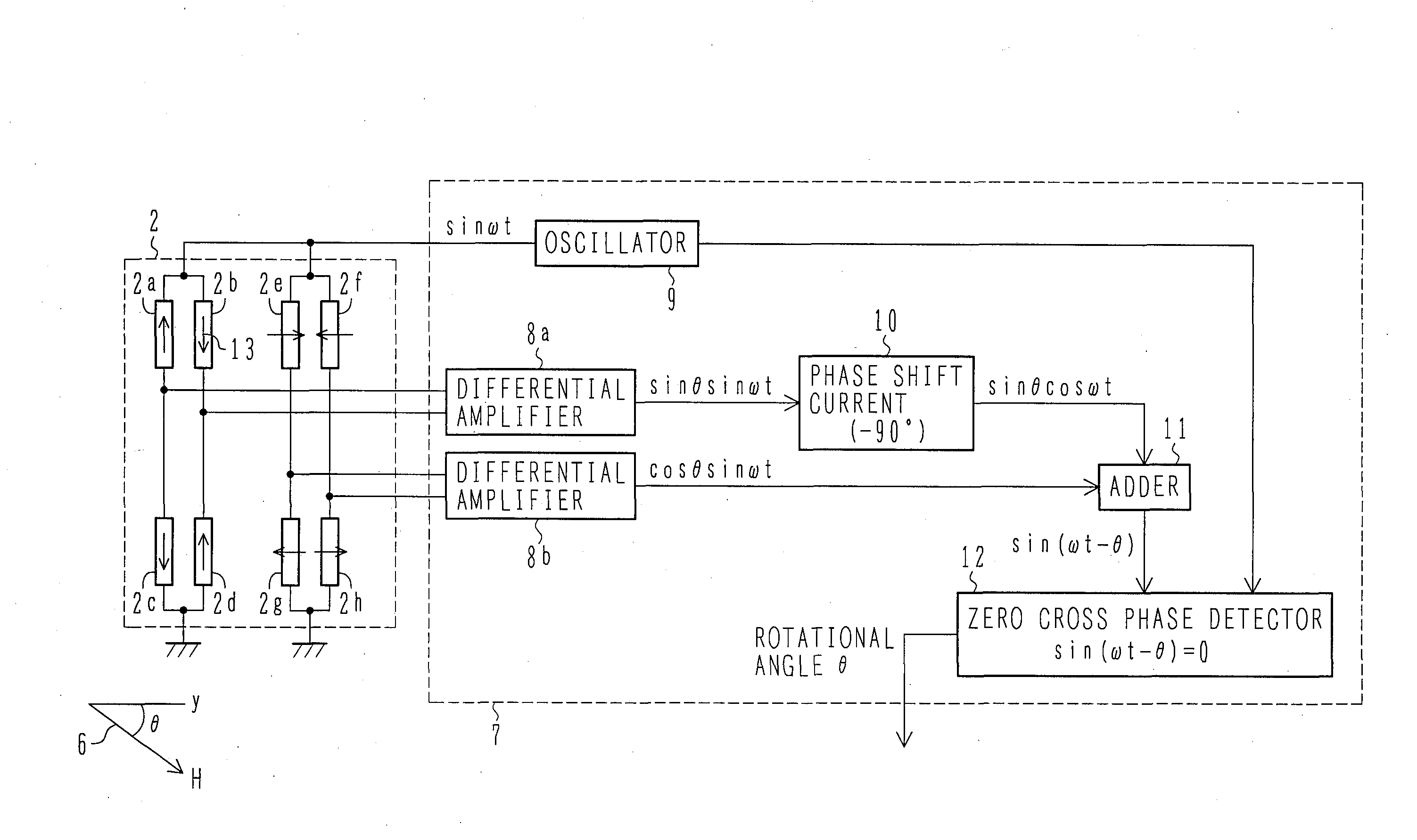
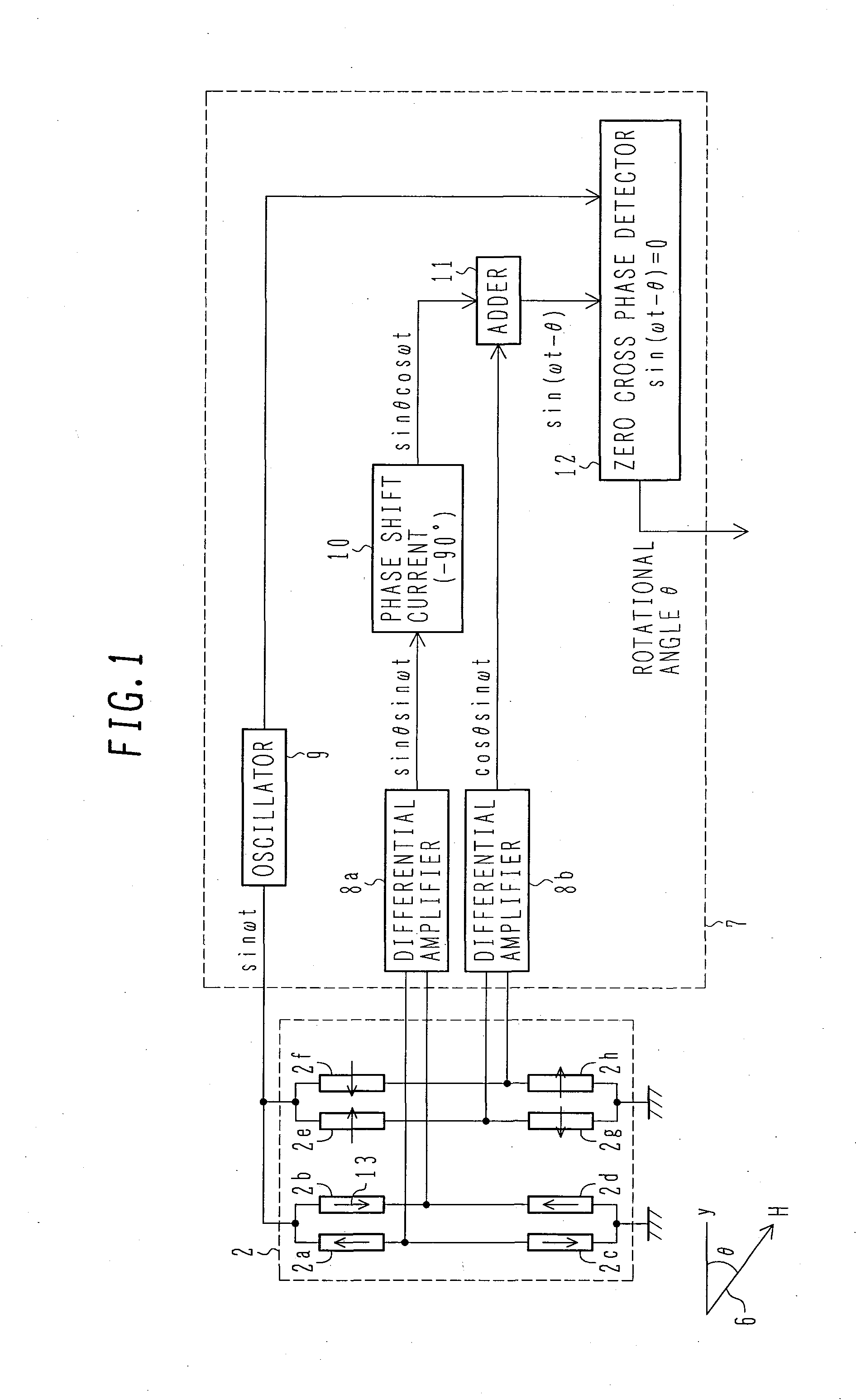
[0086]FIG. 1 is a block diagram of the rotational angle sensor of the present invention.
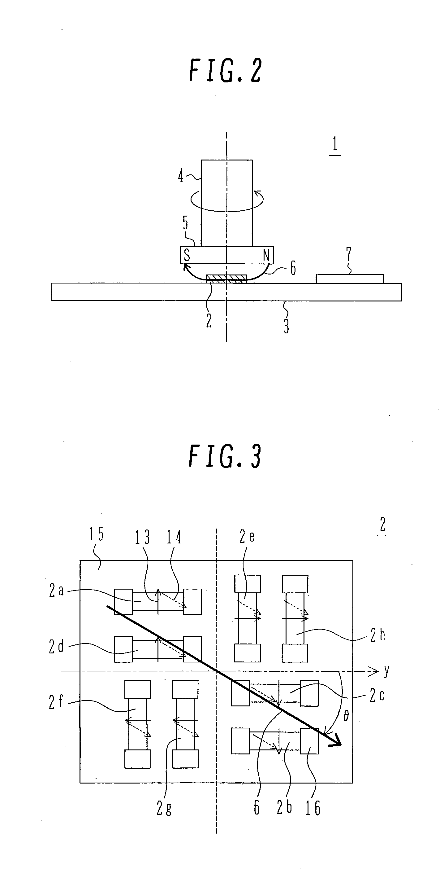
[0087]Each GMR element is wired (not shown) so as to constitute the two Wheatstone bridge circuits shown in FIG. 1, i.e., a first Wheatstone bridge circuit comprising four GMR elements 2a, 2b, 2c and 2d, the GMR elements 2a, 2b, 2c and 2d each having a fixed magnetic layer set in a predetermined magnetization direction parallel or anti-parallel with respect to the reference direction y of the rotational angle, and a second Wheatstone bridge circuit comprising four GMR elements 2e, 2f, 2g and 2h, the GMR elements 2e, 2f, 2g and 2h each having a fixed magnetic layer set in a predetermined ±90° magnetization direction with respect to the reference direction y of the rotational angle.
[0088]As is seen from a sectional structure shown in FIG. 4, each GMR element is constituted by a laminate, the laminate comprising, on a non-magnetic substrate 15, an underlayer 17, an antiferromagnetic layer 18, a fixe...
second embodiment
[0111]FIG. 8 is a block diagram of a rotational angle sensor according to the present invention.
[0112]In this second embodiment, a GMR element sensor section 2 is of the same construction as that in the first embodiment, with a signal processing section 7 in the second embodiment being different in construction from that used in the first embodiment.
[0113]When the AC voltage sin(ωt) is applied from the oscillator circuit 9 to the first and second Wheatstone bridge circuits in the GMR element sensor section 2, an AC-modulated output signal sin θ sin(ωt) is obtained from the first Wheatstone bridge circuit (GMR elements 2a, 2b, 2c and 2d) through the differential amplifier 8a, while an AC-modulated output signal cos θ sin(ωt) is obtained from the second Wheatstone bridge circuit (GMR elements 2e, 2f, 2g and 2h) through the differential amplifier 8b.
[0114]Next, a phase variable φ(0→θ) is generated from a sequential phase generator circuit 27, and cos φ and sin φ are generated from a s...
third embodiment
[0117]FIG. 9 is a block diagram of a rotational angle sensor according to the present invention.
[0118]In this third embodiment, a description will be given about a method for correction in the case where the reference rotational direction y of the rotor section and the magnetization direction 13 of the fixed magnetic layer which is a reference direction of the GMR element sensor section 2 deviate from each other by a variation angle α.
[0119]Ideally, the deviation angle α is required to be zero. However, it does not become zero due to, for example, variations in the manufacturing process and mounting. It is presumed that such variations occur mainly in a magnetizing process for setting the magnetization direction 13 of the fixed magnetic layer in each GMR element, an etching process at the time of forming a resistance pattern of each GMR element, an integral mounting process of each GMR element substrate, and an assembling process of the stator section and the rotor section.
[0120]The...
PUM
 Abstract
Description
Claims
Application Information
 - R&D
- Intellectual Property
- Life Sciences
- Materials
- Tech Scout
- Unparalleled Data Quality
- Higher Quality Content
- 60% Fewer Hallucinations
Browse by: Latest US Patents, China's latest patents, Technical Efficacy Thesaurus, Application Domain, Technology Topic, Popular Technical Reports.
© 2025 PatSnap. All rights reserved.Legal|Privacy policy|Modern Slavery Act Transparency Statement|Sitemap|About US| Contact US: help@patsnap.com


