
Servo Control Apparatus

a technology of servo control and control apparatus, which is applied in the direction of program control, electric controller, instruments, etc., can solve the problems of tracking error when speed and/or acceleration change significantly, command error and control object output, etc., and achieve high trackability, high trackability, and high trackability

Inactive Publication Date: 2008-05-15
YASKAWA DENKI KK
View PDF6 Cites 11 Cited by
  • Summary
  • Abstract
  • Description
  • Claims
  • Application Information

AI Technical Summary

Benefits of technology

[0032] According to one aspect of the present invention, a compensation signal for compensating so that the error of the target command and the output of the controlled object at the time of the acceleration / deceleration change becomes small is generated and sent to the controlled object. Therefore, there is an effect that the controlled object can be controlled at high traceability even if speed and / or acceleration changes sharply.
[0045] According to another aspect of the present invention, even if the controller is a PID controller which decides the control input by any one of proportionality, integral and differential operation of an error of the target command and the position of the motor, or a combination thereof, the compensation signal arithmetic unit which generates a compensation signal for compensating so that the error of the target command and the output of the controlled object at the time of acceleration / deceleration changes becomes small receives the target command increment value, subtracts the target command increment value from the output of the inverse transfer function unit having an inverse transfer function characteristic of an arbitrarily decided low-pass filter arbitrarily, and sends the signal in which an adjustment gain is multiplied to the controlled object as a compensation signal. Therefore, there is an effect that the controlled object can be controlled at high trackability even if speed and / or acceleration changes sharply.

Problems solved by technology

However, although a conventional servo control apparatus can decrease the error of a target command and a controlled object output, since a signal in which an command increment value is filtered is used as a target command increment value, there was a problem that a delay arose between the command increment value and the target command increment value, resulting in an error of a command and a controlled object output.
Moreover, when a command increment value is used as a target command increment value without filtering, although no delay may occur between the command and the target command, a tracking error will occur when speed and / or acceleration changes significantly.

Method used


Image

  • Servo Control Apparatus
  • Servo Control Apparatus
  • Servo Control Apparatus

Examples


Embodiment Construction

[0060] Embodiments of the present invention will be detailed with reference to drawings.

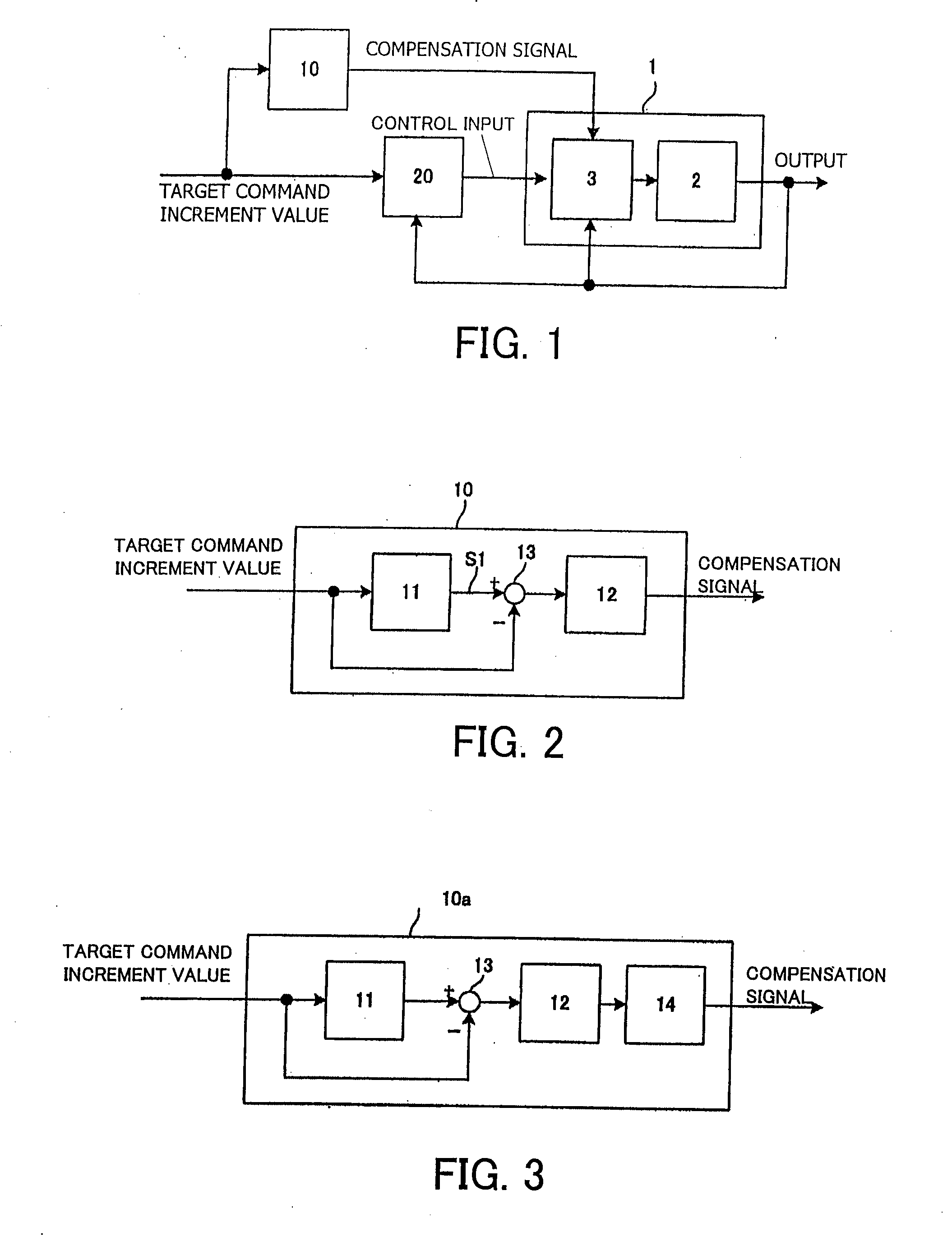
[0061]FIG. 1 is a block diagram showing a structure of a servo control apparatus according to the present invention. As shown in this figure, this servo control apparatus is equipped with a compensation signal arithmetic unit 10 and a predictive controller 20 to control a controlled object 1.

[0062] The compensation signal arithmetic unit 10 generates a compensation signal based on a target command increment value given from an upstream command device (not illustrated), i.e., an increment value in a sampling period of the target command.

[0063] The predictive controller 20 receives the target command increment value and an output of the controlled object 1, performs a predetermined operation to generate a control input, and inputs the control input into the controlled object 1. At this time, the predictive controller 20 determines the control input so as to minimize the evaluation function regar...


PUM


Abstract

A servo control apparatus improved in trackability without being accompanied by overshoots or any continuous vibration and capable of tracking without any delay from an upper order command is provided. A command signal is directly transmitted to a controller as a target command increment value. A compensation signal arithmetic unit receives the target command increment value, subtracts the target command increment value from a signal having passed through an inverse transfer function unit having an inverse transfer function characteristic of any low-pass filter, and sends a compensation signal generated by multiplying a result of that subtraction by an adjustment gain to a controlled object. The controller receives the target command increment value and an output increment value of the controlled object, and sends a control input to the controlled object so that the output of the target command becomes coincident with the target command.

Description

FIELD OF THE INVENTION [0001] The present invention relates to a servo control apparatus for driving, e.g., a machine tool, a semiconductor producing equipment, or a mounting apparatus, which require high command trackability. BACKGROUND OF THE INVENTION [0002] A servo control apparatus which gives a control input to a controlled object to make an output of the controlled object coincide with the targeted value of the control input, is known (see Japanese Patent No. 3175877 ('877 patent), International Laid-open Patent Publication No. WO93 / 20489 ('489 patent).) [0003]FIG. 10 is a block diagram showing a structure of a servo control apparatus disclosed by the '877 patent. This is a motor control apparatus which includes a predictive controller 61 and a controlled object 1, and the controlled object 1 includes a motor controller 3 and a motor 2. The output of the predictive controller 61 and the output of the motor 2 are inputted into the motor controller 3, and a target command incre...

Claims


Application Information

Patent Timeline
Patent Type & Authority Applications(United States)
IPC IPC(8): G05B11/36G05B5/01G05B11/32G05B13/04H02P29/00
CPCG05B5/01G05B2219/41121G05B13/042
Inventor OHTA, SEITARONAKAMURA, HIROSHIIMADU, ATSUSHI
Owner YASKAWA DENKI KK
Learn More