
Method of Stimulating Oil and Gas Wells Using Deformable Proppants

a technology of deformation and proppant, which is applied in the direction of fluid removal, borehole/well accessories, chemistry apparatus and processes, etc., can solve the problems of loss of proppant pack width, failure of proppant, formation rock, etc., and achieves the effect of minimizing the damage of the proppant pack, improving the permeability of the retained proppant pack, and improving the production of wells

Active Publication Date: 2008-05-15
BAKER HUGHES HLDG LLC
View PDF27 Cites 9 Cited by
  • Summary
  • Abstract
  • Description
  • Claims
  • Application Information

AI Technical Summary

Benefits of technology

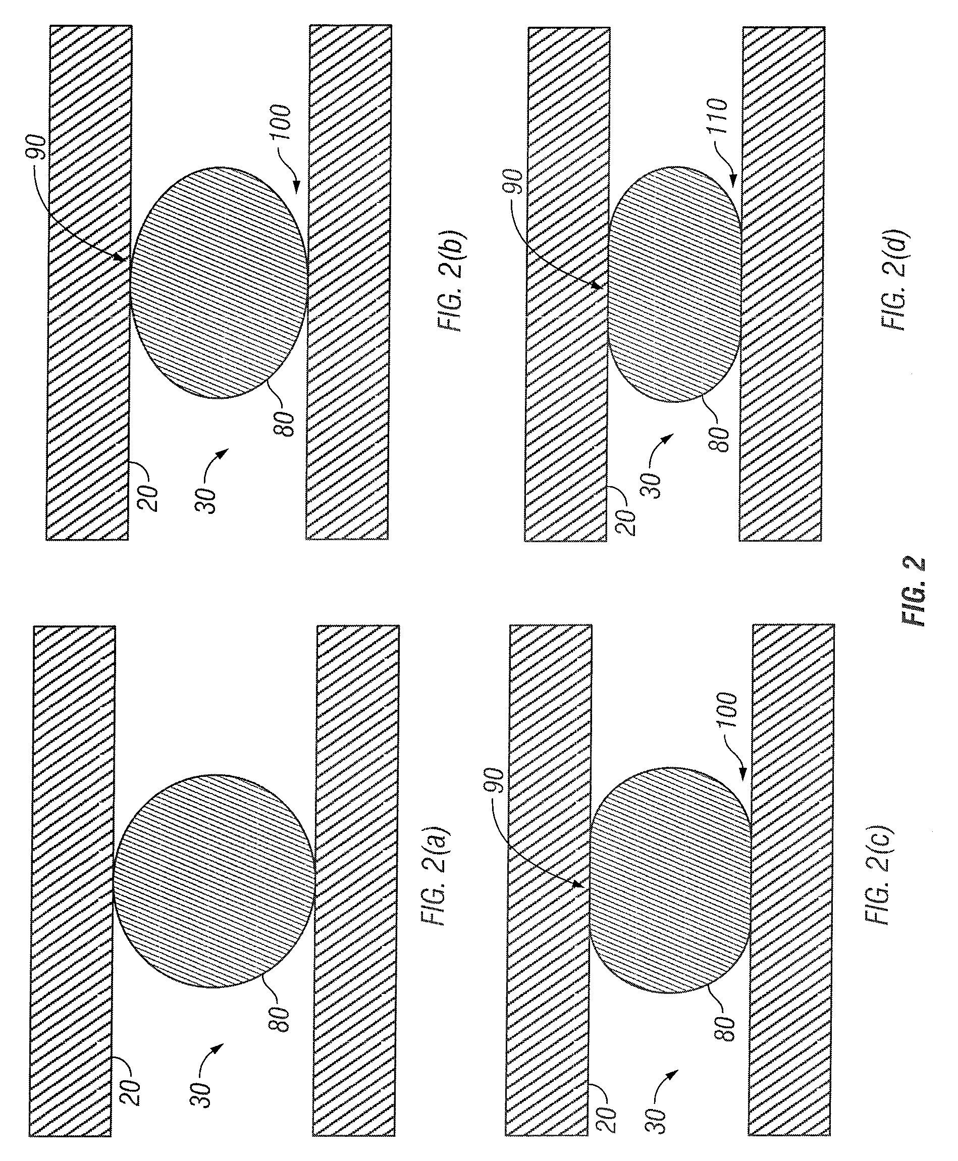
Deformable proppants effectively reduce proppant pack damage and fines generation, enhancing well productivity by maintaining permeability and conductivity even at elevated stress levels, thus extending the closure stress range for fracturing operations.

Problems solved by technology

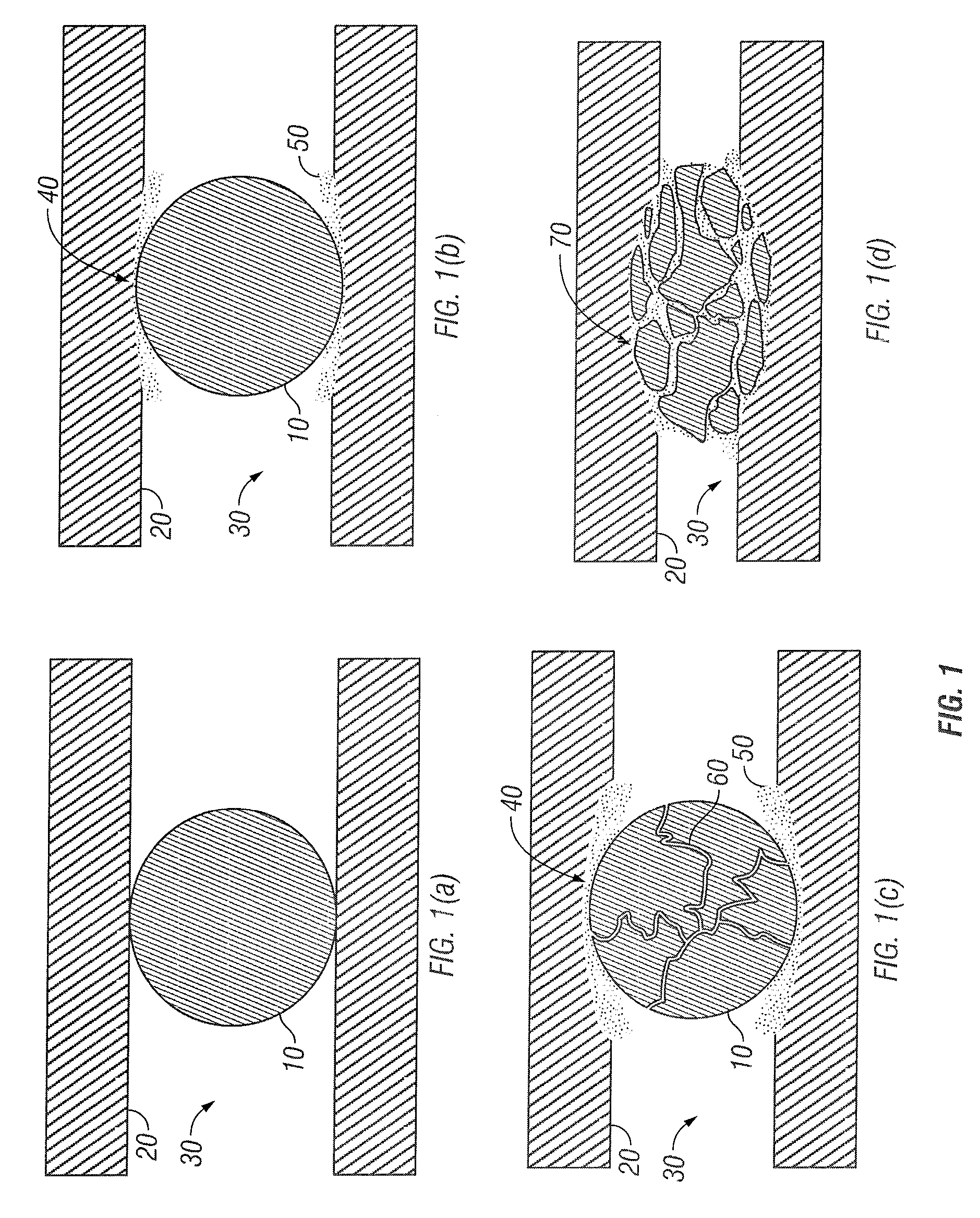
Proppant pack conductivity damage from embedment results in loss of proppant pack width as the proppant embeds into the rock and proppant pack pore throats are plugged by displaced formation fines.
Such fines are generated at the fracture-face to proppant pack interface as in situ closure stresses acting upon the fracture cause failure of the proppant, the formation rock, or both.
Further, fines composed of formation material (e.g., shale, sand, coal fines, etc.) may present similar problems and may be produced, for example, within the fractured formation due to stresses and forces applied to the formation during fracturing.
However, at elevated stress levels, the permeability and porosity levels of such proppant packs are compromised by embedment and spalling.

Method used


Image

  • Method of Stimulating Oil and Gas Wells Using Deformable Proppants
  • Method of Stimulating Oil and Gas Wells Using Deformable Proppants
  • Method of Stimulating Oil and Gas Wells Using Deformable Proppants

Examples


examples

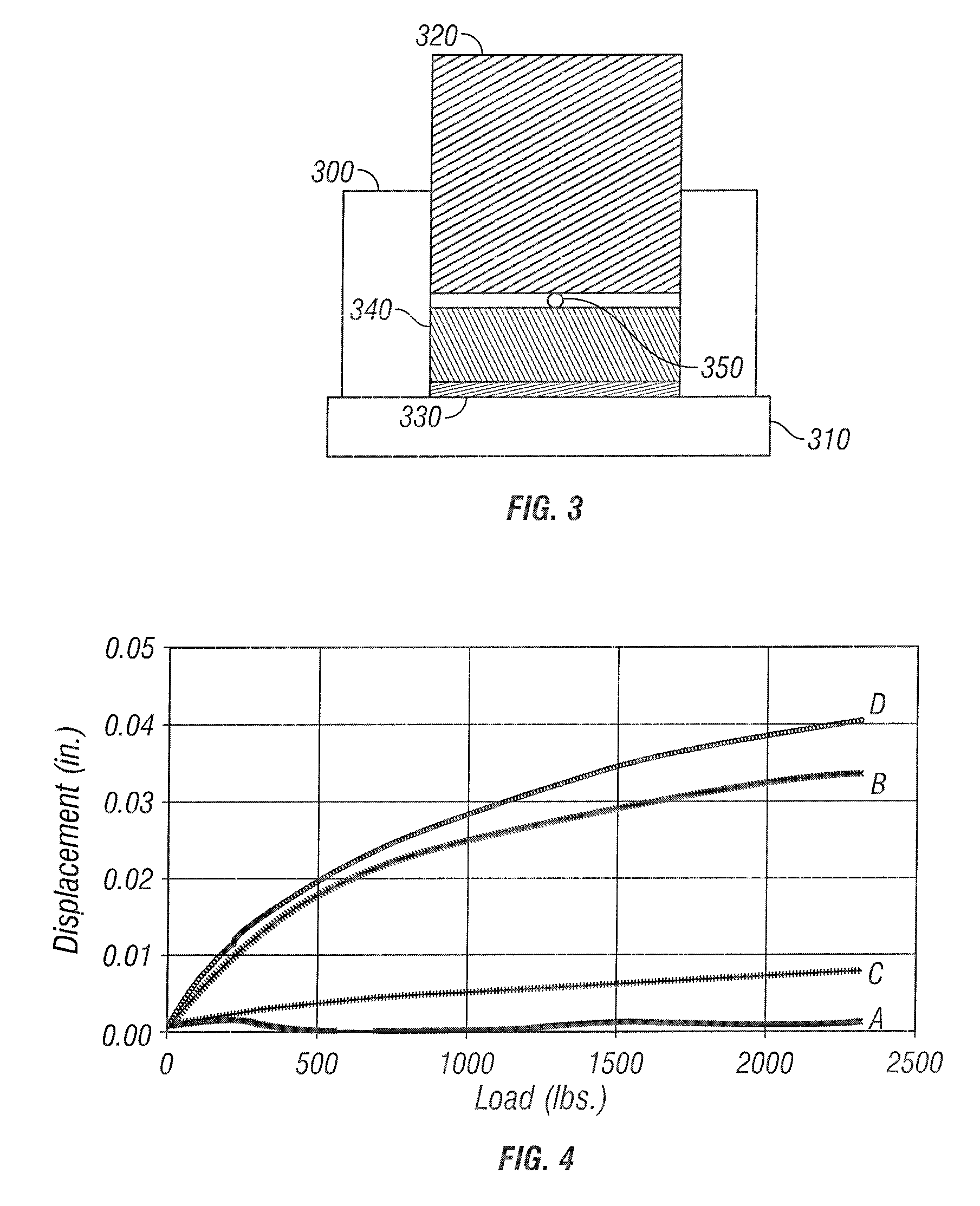
[0065] The degree of embedment of 20 / 40 (mesh size) LiteProp™ 125 and 20 / 40 Ottawa sand was determined by compressing a partial mono-layer (i.e., 43 particles / in2) of proppant against a shale core and measuring the displacement of a steel piston as a function of applied load, as exemplified in FIG. 3. The test, or embedment, cell was composed of a thick-walled stainless steel cylinder 300 and base plate 310, a 1-inch diameter steel piston 320, porous plate 330 on which the core sample 340 was placed. The proppant 350 was placed against core sample 340. Steel piston 320 pressed proppant 350 into core sample 340, and its displacement was used to infer proppant embedment.

[0066] Embedment was inferred by subtracting out the displacements of the core, test cell, and proppant compression. Mathematically, embedment (Δxemb) was calculated from the following expression:

(Δxemb)=(Δxgross)−(Δxsys)−(Δxcore)−(Δxprop)  (1)

[0067] Details of the steps taken to infer embedment were as follows:

[00...


PUM

PropertyMeasurementUnit
elastic modulusaaaaaaaaaa
specific gravityaaaaaaaaaa

Abstract

A method of fracturing using deformable proppants minimizes proppant pack damage, without compromising the fracturing fluid's proppant transport properties during pumping, by use of deformable proppants. Selection of proppant is dependent upon the mechanical properties of the formation rock. The strength of the deformable proppant is dependent upon the modulus of the formation rock being treated such that the proppant is capable of providing, at the very least, a minimum level of conductivity in in-situ stress environments. The maximum elastic modulus of the deformable proppant is less than the minimum modulus of the formation rock which is being treated. The method is particularly applicable in fracturing operations of subterranean reservoirs such as those comprised primarily of coal, chalk, limestone, dolomite, shale, siltstone, diatomite, etc.

Description

[0001] This application is a continuation application of U.S. application Ser. No. 11 / 034,388, filed on Jan. 12, 2005.FIELD OF THE INVENTION [0002] The invention relates to a method of fracturing using deformable proppants in order to minimize fines generation and proppant pack damage. The method of the invention has particular applicability in the fracturing of subterranean reservoirs such as those comprised primarily of coal, chalk, limestone, dolomite, shale, siltstone, diatomite, etc. BACKGROUND OF THE INVENTION [0003] Hydraulic fracturing is a common stimulation technique used to enhance production of fluids from subterranean formations. In a typical hydraulic fracturing treatment, fracturing treatment fluid containing a solid proppant is injected into the wellbore at pressures sufficient to create or enlarge a fracture in the reservoir. The proppant is deposited in the fracture, where it remains after the treatment is completed. The proppant serves to hold the fracture open, t...

Claims


Application Information

Patent Timeline
Patent Type & Authority Applications(United States)
IPC IPC(8): E21B43/267C09K8/80
CPCC09K8/80E21B43/267C09K8/805
Inventor BRANNON, HAROLD DEANRICKARDS, ALLAN RAYSTEPHENSON, CHRISTOPHER JOHNMAHARIDGE, RUSSELL L.
Owner BAKER HUGHES HLDG LLC
Learn More