
Multiple-input multiple-output communication system

a communication system and multi-input technology, applied in multiplex communication, wireless communication, phase-modulated carrier systems, etc., can solve the problems of linear increase of the number of mimo channels, the linear increase of the number of costly electrical-to-optical converters and optical-to-electric converters, and the difficulty of providing a specific base station for each cell. to achieve the effect of increasing the price competitiveness

Inactive Publication Date: 2008-05-08
SAMSUNG ELECTRONICS CO LTD
View PDF4 Cites 37 Cited by
  • Summary
  • Abstract
  • Description
  • Claims
  • Application Information

AI Technical Summary

Benefits of technology

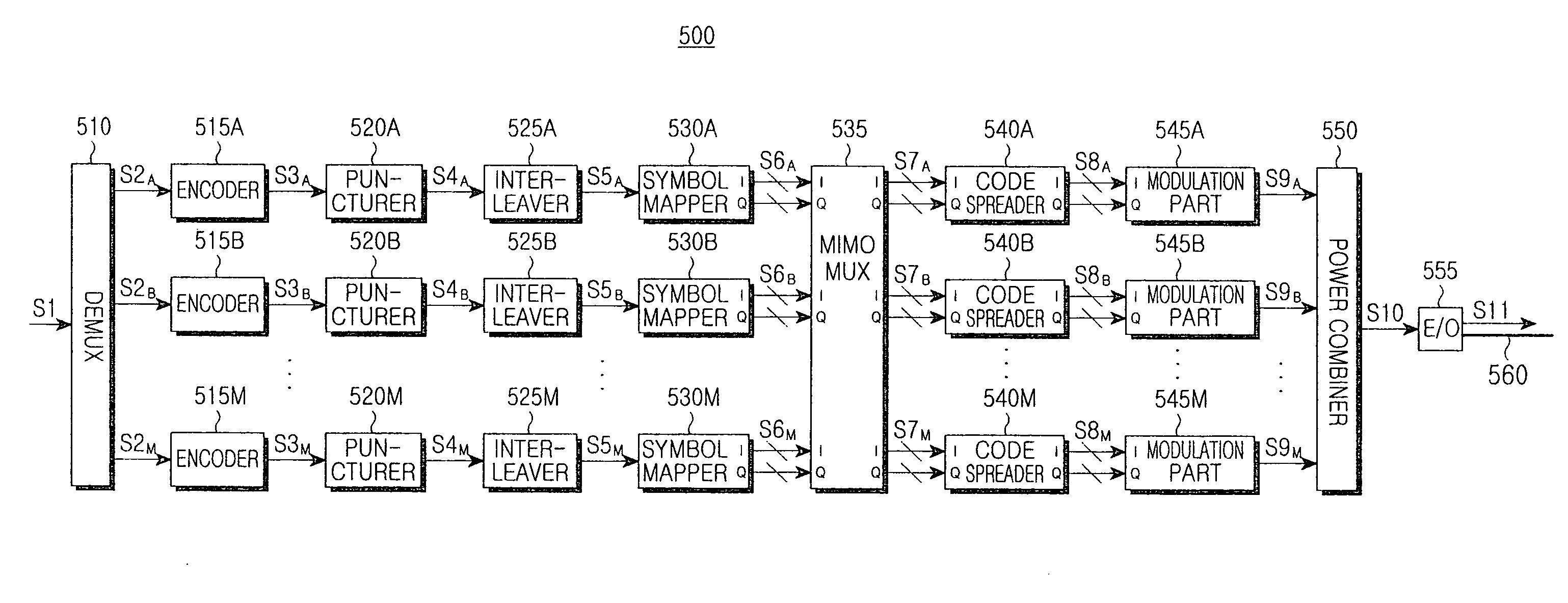
The present invention provides a MIMO communication system that increases price competitiveness when adopting a wire transmission scheme. The system includes a base station and a relay station connected through an optical fiber, and wirelessly transmits signals through multiple antennas. The base station has multiple symbol mappers, a multi-input / multi-output multiplexer, and a plurality of code spreaders. The system allows for efficient and reliable wireless communication at a competitive cost.

Problems solved by technology

However, the costs to install and maintain base stations are high, so it is quite difficult to provide a specific base station for each cell.
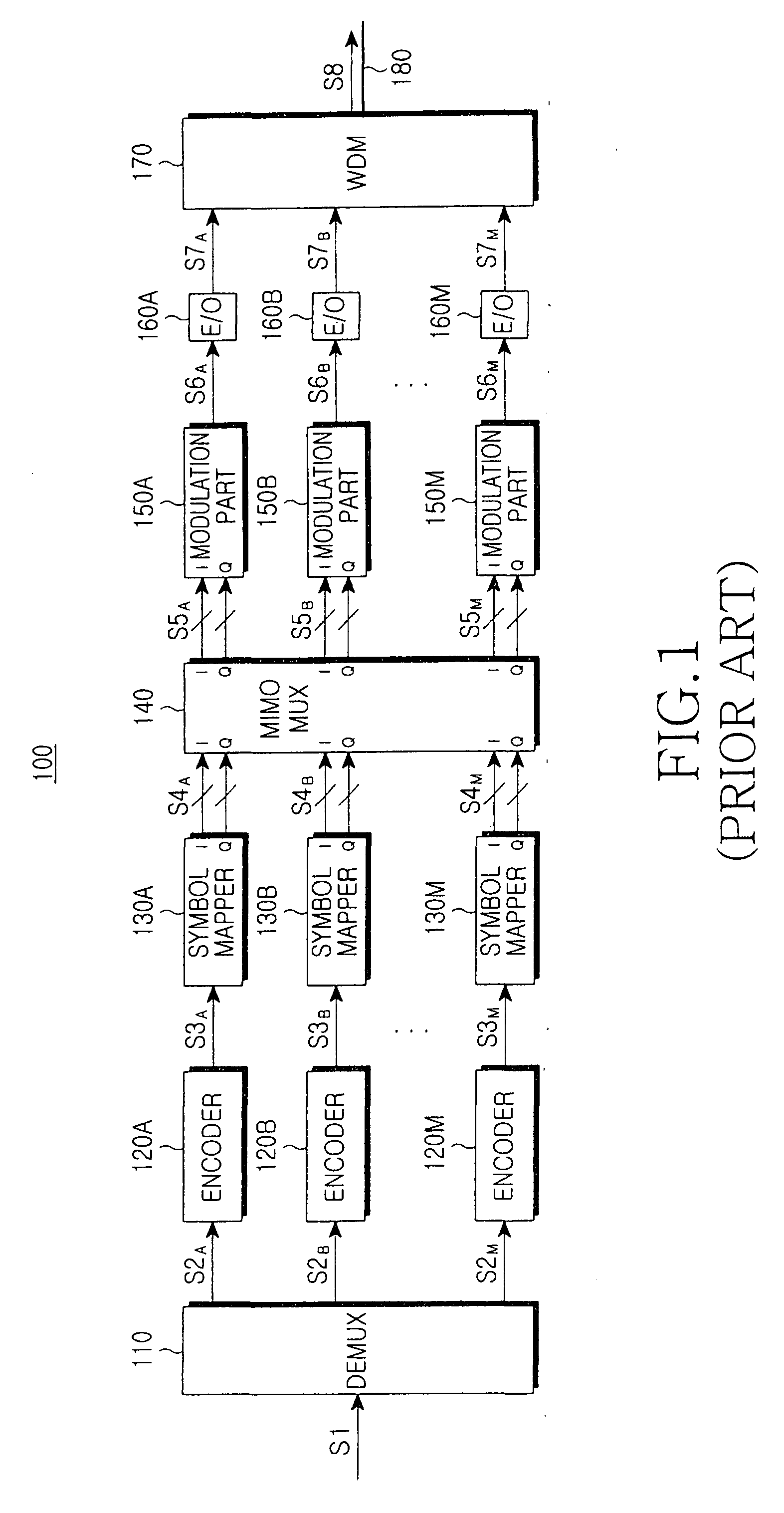
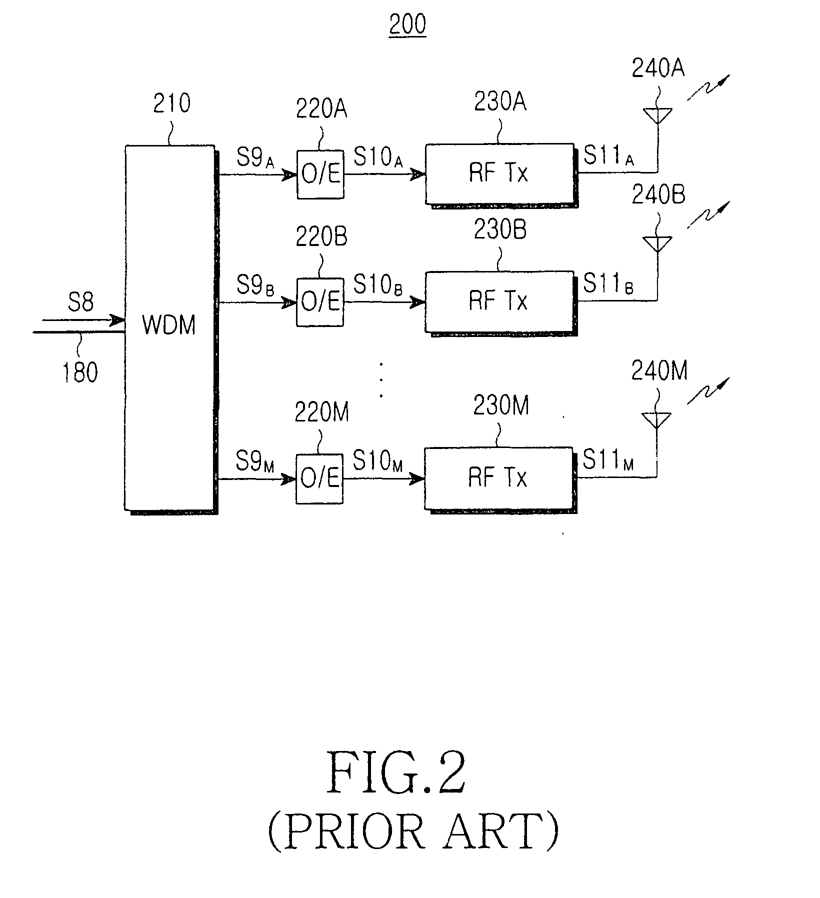
However, the aforementioned MIMO communication system has a problem in that the number of costly electrical-to-optical converters and optical-to electrical converters will linearly increase with a corresponding increase in the number of MIMO channels, i.e. the number of antennas.
In addition, the MIMO communication system should be provided with a wavelength division multiplexer and wavelength division demultiplexer, which are expensive, thereby causing a decrease in price competitiveness, and a lack of such WDMs will contribute to signal loss.
However, providing such means will also complicate the structure of the systems.

Method used


Image

  • Multiple-input multiple-output communication system
  • Multiple-input multiple-output communication system
  • Multiple-input multiple-output communication system

Examples


Embodiment Construction

[0028]Hereinafter, exemplary embodiments of the present invention will be described with reference to the accompanying drawings. It should be understood that the examples disclosed herein have been provided for purposes of illustration and not for limitation. Further, for the purposes of clarity and simplicity, a detailed description of known functions and configurations incorporated herein will be omitted so as not to obscure the subject matter of the present invention.

[0029]FIGS. 3 and 4 collectively illustrate a MIMO communication system according to a first exemplary embodiment of the present invention. The MIMO communication system (300 and 400) includes a base station 300 connected through an optical fiber 360, which is shown in FIG. 3, and a relay station 400, which is shown in FIG. 4. The base station 300 transmits an optical signal S12 to the relay station 400, and the relay station 400 engages in electrical-to-optical conversion for the optical signal S12 received from the...


PUM


Abstract

A multiple-input multiple-output (MIMO) communication system includes a base station and a relay station that are connected through an optical fiber. The relay station wirelessly transmits through a plurality of antennas a signal received from the base station. The base station includes a plurality of symbol mappers for mapping input bit streams into a plurality of symbol signals; a MIMO multiplexer generating a plurality of exchange signals by exchanging bits of the symbol signals; and a plurality of code spreaders generating a plurality of spread signals by band spreading the exchange signals. The adoption of a wire transmission scheme for connecting the base station with the relay station through a single optical fiber provides benefits in cost reduction and complexity as the number of electrical-to-optical converters is reduced, and the bandwidth is superior to those in wireless transmission scheme

Description

CLAIM OF PRIORITY[0001]This application claims the benefit under 35 U.S.C. §119(a) from an application entitled “Multiple-input Multiple-Output Communication System,” filed in the Korean Intellectual Property Office on Nov. 7, 2006 and assigned Serial No. 2006-109401, the contents of which are hereby incorporated by reference in its entirety.BACKGROUND OF THE INVENTION[0002]1. Field of the Invention[0003]The present invention relates to a wireless communication system. More particularly, the present invention relates to a multiple-input multiple-output (MIMO) communication system, which performs wireless communication using a plurality of antennas.[0004]2. Description of the Related Art[0005]With the continued increase in demand for high-speed data services from various users, the technological development of a physical layer capable of transmitting more data using limited communication resources is of the highest priority in order to provide users with more services at lower cost. ...

Claims


Application Information

Patent Timeline
Patent Type & Authority Applications(United States)
IPC IPC(8): H04B7/02
CPCH04B7/0413H04L27/18H04J13/00H04B10/2575H04W88/08
Inventor LEE, HAN-LIMHAN, SHUANGFENGOH, YUN-JEHWANG, SEONG-TAEKKIM, HOON
Owner SAMSUNG ELECTRONICS CO LTD
Learn More