Punch stripper and press tool

a technology of punching tool and punching hole, which is applied in the field of punching tool and press tool, can solve the problems of increased wear on press tools, press tool components, and need for maintenance monitoring, so as to reduce the risk of errors and damage to equipment and personnel

Inactive Publication Date: 2008-05-08
STROMSHOLMEN
View PDF11 Cites 13 Cited by
  • Summary
  • Abstract
  • Description
  • Claims
  • Application Information

AI Technical Summary

Benefits of technology

[0026] In accordance with one non-limiting aspect of the present invention, a punch stripper is provided which is adapted to be fastened to a punch retainer in a press tool. The punch retainer comprises a punch stripper piston and a pressure chamber adapted to spring-load the punch stripper piston. The pressure chamber is defined by a gap between an inner sleeve and an outer sleeve. The punch stripper piston has a portion that is axially displaceable in the gap. Substantially, the whole pressure chamber is located within the outer sleeve. As defined herein, “substantially the whole pressure chamber” means the space that forms the pressure chamber, excluding any ducts for charging / discharging gas or for interconnection with other, similar punch strippers. By using a pressure chamber, a larger initial force can be obtained. The larger force can be used to improve the punch performance in high-strength sheet metal; however, this is not required. By employing gas spring technology and forming the pressure chamber between the inner sleeve and the outer sleeve assembly, a more compact assembly than existing assemblies can be obtained; however, this is not required. The more compact assembly is advantageous since there is often little available space in today's press tools. By regulating the pressure in the chamber, the stripping force required can be easily altered and a minimal number of variants of the punch stripper can be achieved; however, this is not required. In addition, the use of gas spring technology can enhance punching process reliability, since it allows for the provision of a larger stripping force and a better way of ensuring that the punching operation is carried out adequately and with the desired quality; however, this is not required. Moreover, the massive generation of force caused by mechanical springs can be avoided; however, this is not required. The use of the gas spring technology of the present invention allows inclined holes and contours to be punched with the same reliability and quality as a traditional punch stripper having a straight contour, since a gas spring-based punch stripper withstands a side load generated by an angle of up to 10°, and under certain conditions up to about 15-20°, and has the same useful life as when used for punching straight holes; however, this is not required. By causing the punch stripper piston to act on a pressure chamber, improved absorption of the shock force generated when the punch pierces the work piece can be obtained; however, this is not required.
[0038] Still another non-limiting object of the present invention is to provide a punch stripper that minimizes the risk of errors and the risk of damage to equipment and personnel in the vicinity of the punch stripper.

Problems solved by technology

Should the punching operation be carried out without a stripper or with too small a stripping force, there is an immediate risk of the metal sheet around the punched hole being deformed during the return movement, since the metal sheet due to friction tends to follow the movement of the punch.
Faster press procedures also result in greater wear on the presses, press tools and press tool components, which means that the need for maintenance has to be monitored.
Both variants are associated with problems and limitations.
A further limitation is the useful life of mechanical springs, which may be slightly too short to meet the increasing demands in the sheet metal forming industry.
Thus, the useful life is a greater limitation for polyurethane.
Another limitation is the ability of the polyurethane to withstand repeated stress while maintaining its dimensions, since the material is susceptible to compression set or creep.
Therefore, polyurethane elements cannot, without difficulty, accommodate the increased production rate.
Another problem that has been found when the polyurethane element is used as a stripper and enters into direct contact with the metal sheet is that particles from the polyurethane element may adhere to the sheet.
The particles may have a detrimental effect on the quality of the subsequent application of lacquer, since the adhesive capacity of the ink is reduced in those places where the polyurethane has been in contact with the sheet.
The punch stripper shown in U.S. Pat. No. 4,292,869 is, however, very bulky and therefore difficult to use in modern standardized press tools.
A consequence of this design, due to the seal against the punch, is an increased risk of gas leakage.
Thus, the punch stripper shown in U.S. Pat. No. 4,316,399 is too bulky and difficult to use in modern standardized press tools.

Method used


Image

  • Punch stripper and press tool
  • Punch stripper and press tool
  • Punch stripper and press tool

Examples


Embodiment Construction

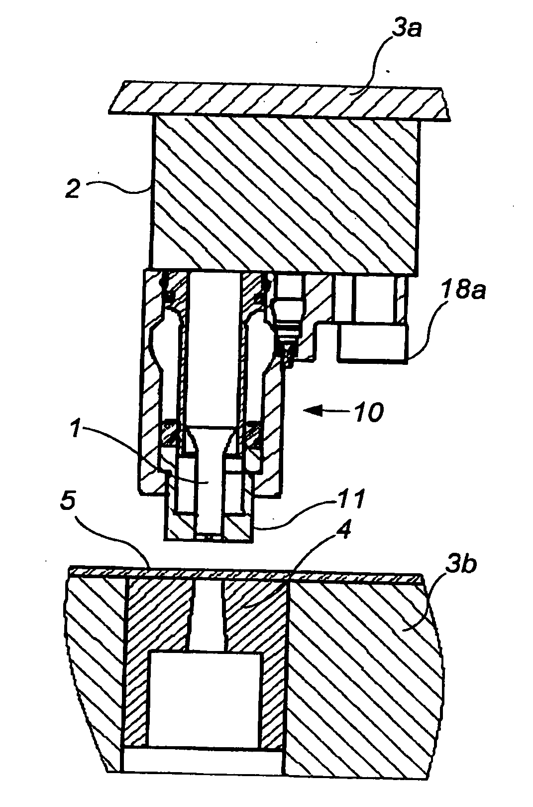
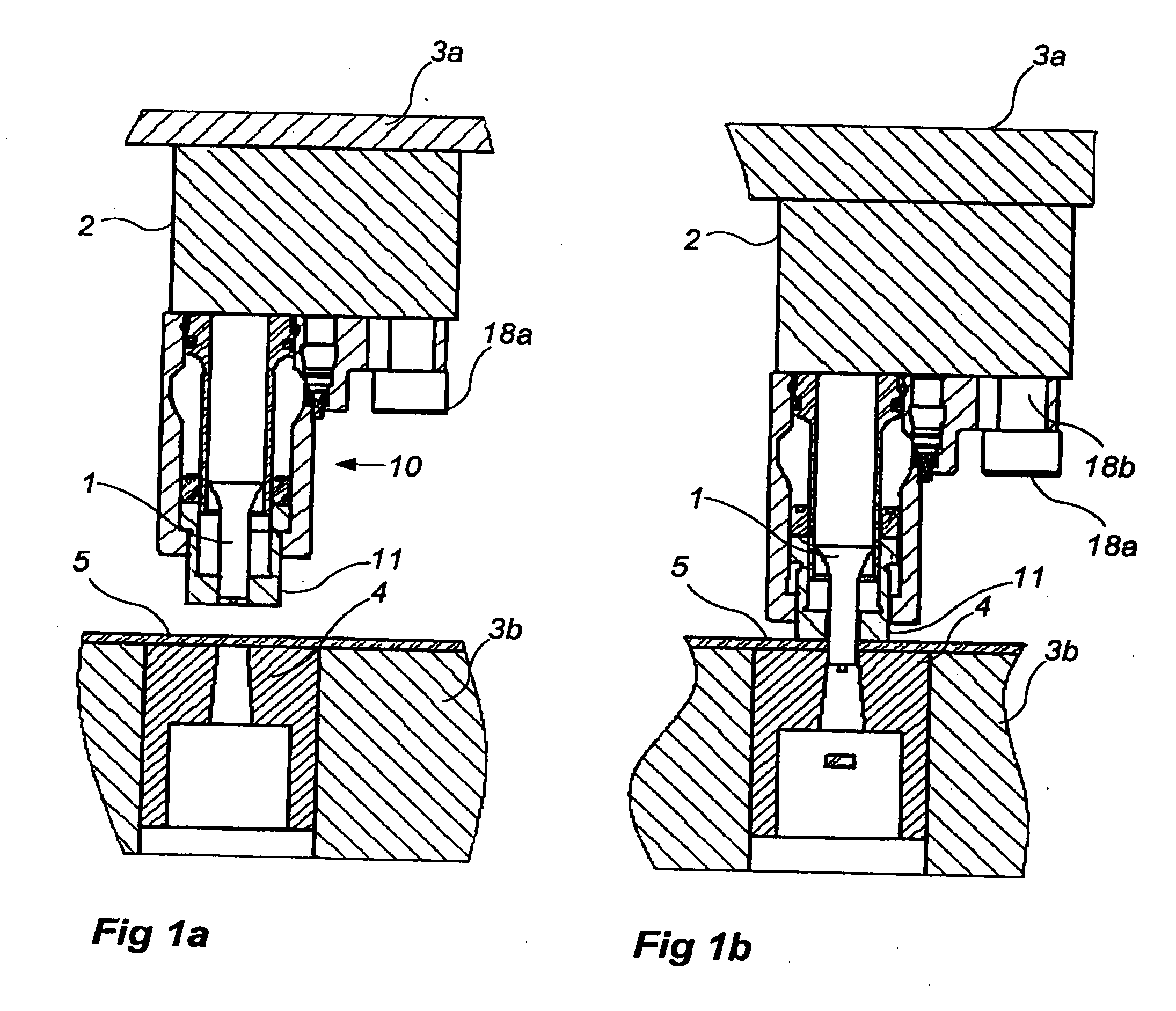
[0047] Referring now to the drawings wherein the showings are for the purpose of illustrating preferred embodiments of the invention only and not for the purpose of limiting same, FIG. 1 illustrates a press tool having an upper tool part 3a and a lower tool part 3b is shown.

[0048] In the lower tool part 3b, a punching die is provided. A work piece 5, which may be a metal sheet, is arranged to be machined by the press tool 3a, 3b.

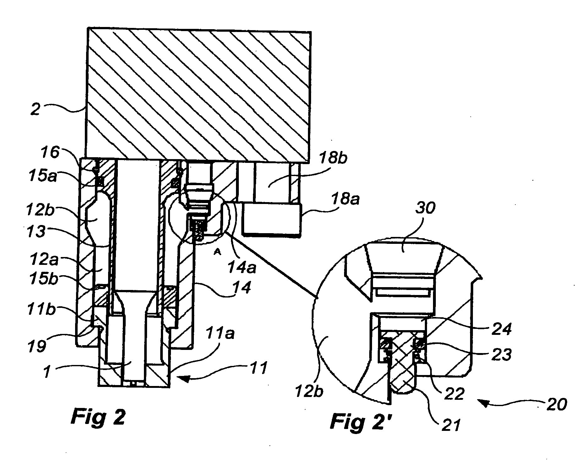
[0049] The upper tool part 3 has a punch retainer 2 on which a punch 1 has a punch stripper that is fastened by means of fastening means 18a, 18b (e.g., screw, bolt, rivet, etc.). The fastening means may, as shown in FIGS. 1a, 1b and 2, be a mounting screw / fastening bolt 18a, whose shank is arranged in a bore 18b in a base portion 14a of the punch stripper.

[0050] In a non-limiting example of the invention, the punch retainer 2 may be designed in any of the ways disclosed in U.S. Pat. No. 6,182,545 B1 (i.e., the punch retainer may have a locking mechanism ...


PUM

PropertyMeasurementUnit
Pressureaaaaaaaaaa
Areaaaaaaaaaaa

Abstract

A punch stripper is adapted to be fastened to a punch retainer of a press tool, and to retain a work piece as the piece is being machined by a punch. The punch stripper includes a punch stripper piston and a pressure chamber adapted to spring-load the punch stripper piston. The pressure chamber is at least partially defined by a gap between an inner sleeve and an outer sleeve. The punch stripper piston has a portion that is axially displaceable in the gap.

Description

[0001] The present invention claims priority on United State Provisional Application Ser. No. 60 / 856,837 filed Nov. 6, 2006, which is incorporated herein by reference. The present invention also claims priority on Swedish Patent Application Serial No. 0602363-4 filed Nov. 6, 2006, which is incorporated herein by reference. [0002] The present invention relates to a punch stripper and to a punching tool that includes a punch stripper. More particularly, the present invention is directed to a punch stripper that is adapted to be fastened to a punch retainer, which in turn may be mounted in a movable upper tool part of a press.BACKGROUND OF THE INVENTION [0003] In the sheet metal forming industry, punching tools are used to punch holes in metal sheets. The punching tool consists primarily of a retainer, a punch and a stripper. The punching tool operates as a closed unit and is often mounted directly in press tools in which the metal sheet is formed, but may also be mounted on shuttles t...

Claims


Application Information

Patent Timeline
IPC IPC(8): B21D45/00
CPCB21D45/006Y10T83/2159
Inventor EKMAN, FREDRIKSTOLTZ, PATRIK
Owner STROMSHOLMEN
Why Eureka
Try Eureka