Light information recording apparatus and light information reproducing apparatus
a light information and recording apparatus technology, applied in the direction of data recording, recording/reproducing/erasing using optical interference patterns, instruments, etc., can solve the problems of difficult to obtain interference fringes with high contrast, difficult to generate beams with uniform light intensity, and difficult to perform separation and combination of beams without deterioration of characteristics by a simple structure. , to achieve the effect of simple structure, small loss in light amount, and improved recording characteristics
- Summary
- Abstract
- Description
- Claims
- Application Information
AI Technical Summary
Benefits of technology
Problems solved by technology
Method used
Image
Examples
first embodiment
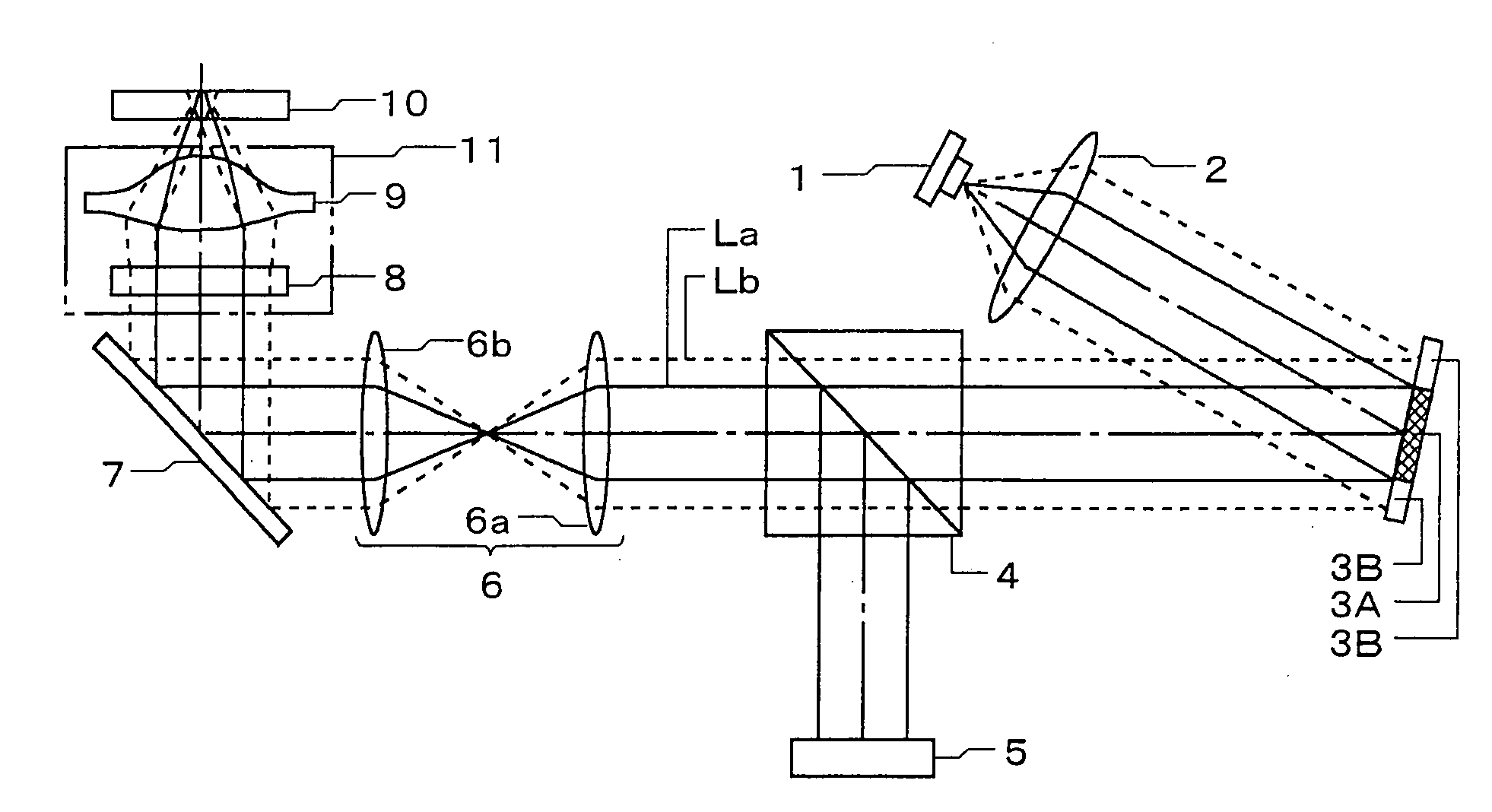
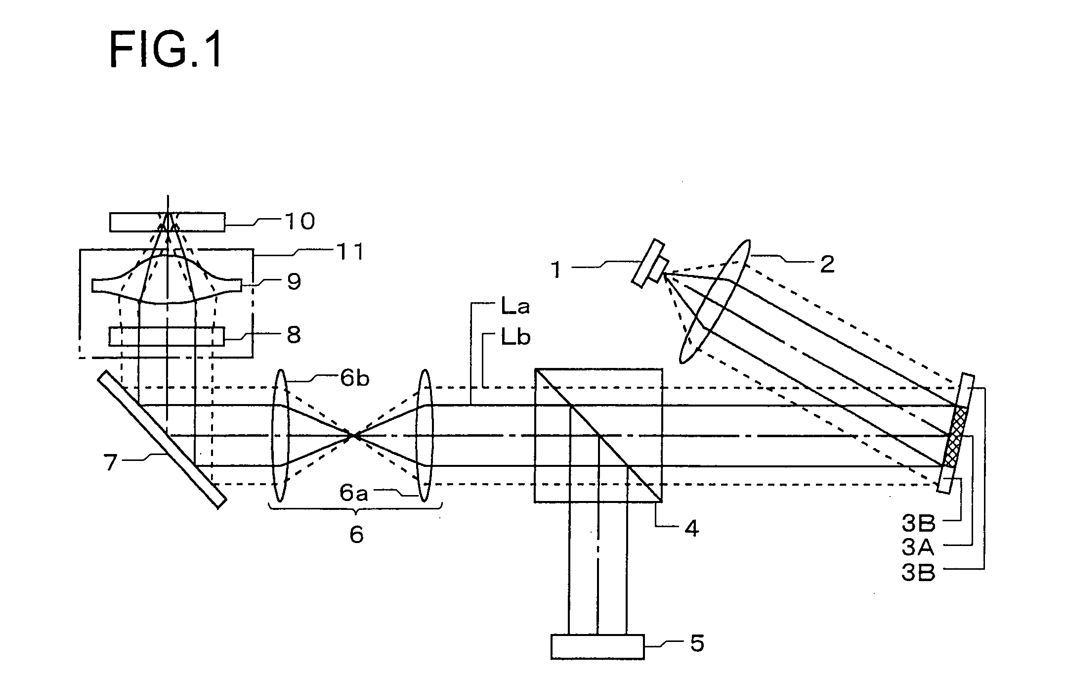
[0018]An optical structure of the light information recording and reproducing apparatus will be explained below in an order along respective light paths at recording information time and reproducing information time. As shown in FIG. 1, when information is recorded, laser beam emitted from the laser light source 1 is converted into parallel beam by the collimator lens 2 and then the beam enters obliquely the spatial light modulator 3A and the mirror 3B. A center part of the laser beam is modulated spatially by the spatial light modulator 3A into information light La, and a peripheral part of the laser beam is reflected by the mirror 3B to make it become reference light Lb for recording.
[0019]The spatial light modulator 3A is a reflective light modulation element which modulates spatially entering light into outgoing light which has two-dimensional digital pattern information. As for one of concrete example of this spatial light modulator 3A, it is possible to give a digital micro-m...
second embodiment
[0036]An optical structure of the light information recording and reproducing apparatus will be explained below in an order along respective light paths at recording information and reproducing information. As shown in FIG. 4A, when information is recorded, laser beam emitted from the laser light source 1 is converted into parallel beam by the collimator lens 2 and then it enters the spatial light modulator 3A and the mirror 3B obliquely. And a center part of the laser beam is modulated spatially by the spatial light modulator 3A into the information light La, and a peripheral part of the laser beam is reflected by the mirror 3B to make it become reference light Lb for recording.
[0037]The spatial light modulator 3A is a reflective light modulation element which modulates spatially entering light into outgoing light which has two-dimensional digital pattern information. As for one of concrete example of this spatial light modulator 3A, it is possible to give a digital micro-mirror d...
PUM
| Property | Measurement | Unit |
|---|---|---|
| transparent | aaaaa | aaaaa |
| light intensity | aaaaa | aaaaa |
| optical structure | aaaaa | aaaaa |
Abstract
Description
Claims
Application Information
 - R&D
- Intellectual Property
- Life Sciences
- Materials
- Tech Scout
- Unparalleled Data Quality
- Higher Quality Content
- 60% Fewer Hallucinations
Browse by: Latest US Patents, China's latest patents, Technical Efficacy Thesaurus, Application Domain, Technology Topic, Popular Technical Reports.
© 2025 PatSnap. All rights reserved.Legal|Privacy policy|Modern Slavery Act Transparency Statement|Sitemap|About US| Contact US: help@patsnap.com


