
Fuel Injector with Direct-Controlled Injection Valve Member with Double Seat

a technology of direct-controlled injection and fuel injector, which is applied in the direction of fuel injection apparatus, machine/engine, feed system, etc., can solve the problems of comparatively long piezoelectric actuators, comparatively complex construction described in de 195 19 191 c1, and the need for piezoelectric actuators with comparatively long li

Inactive Publication Date: 2008-05-01
ROBERT BOSCH GMBH
View PDF8 Cites 9 Cited by
  • Summary
  • Abstract
  • Description
  • Claims
  • Application Information

AI Technical Summary

Benefits of technology

The invention relates to a fuel injector for internal combustion engines that uses a direct-controlled injection valve member with a double seat and a piezoelectric actuator. This design allows for a shorter actuator length and a more compact injector construction. The actuator controls the injection valve member, which has at least two sealing seats, and the nozzle needle is unthrottled for better transmission of the actuator's force. The fuel injector has a high-pressure source for delivering fuel to the combustion chamber, and the nozzle needle is controlled directly by the actuator. This design reduces the required actuator length and allows for optimized injector performance.

Problems solved by technology

However, such injectors require long piezoelectric actuators in order to attain the necessary nozzle needle stroke.
However, the construction described in DE 195 19 191 C1 is comparatively complex, and in particular it has the disadvantage that comparatively long piezoelectric actuators must be used in order to attain the required stroke for the injection event and to unthrottle the nozzle needle.
However, high hydraulic ratios between the actuator stroke and the nozzle needle stroke are usually necessary along with the use of long mechanical connecting parts.
These injectors therefore as a rule have a poorer, indirect transmission behavior of the switching force of the actuator to the nozzle needle.

Method used


Image

  • Fuel Injector with Direct-Controlled Injection Valve Member with Double Seat
  • Fuel Injector with Direct-Controlled Injection Valve Member with Double Seat
  • Fuel Injector with Direct-Controlled Injection Valve Member with Double Seat

Examples


Embodiment Construction

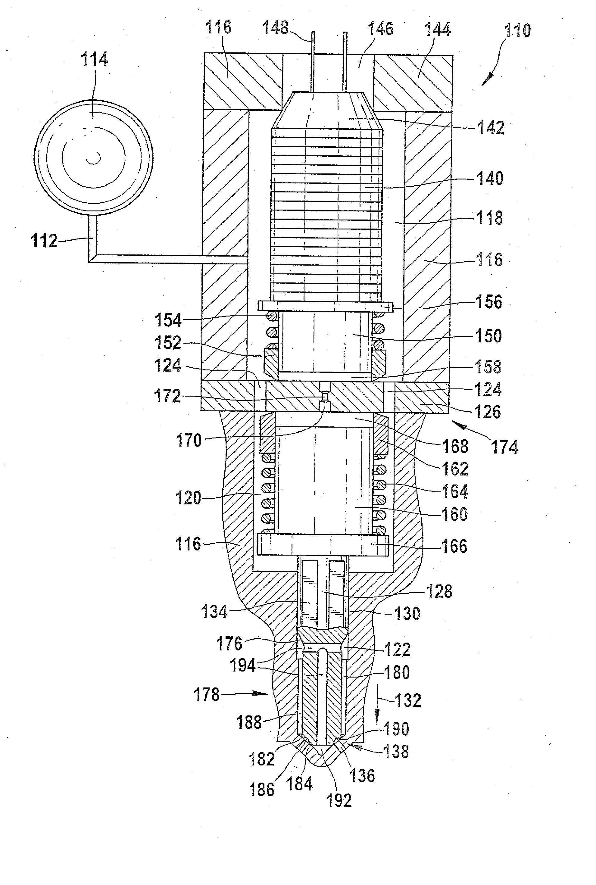
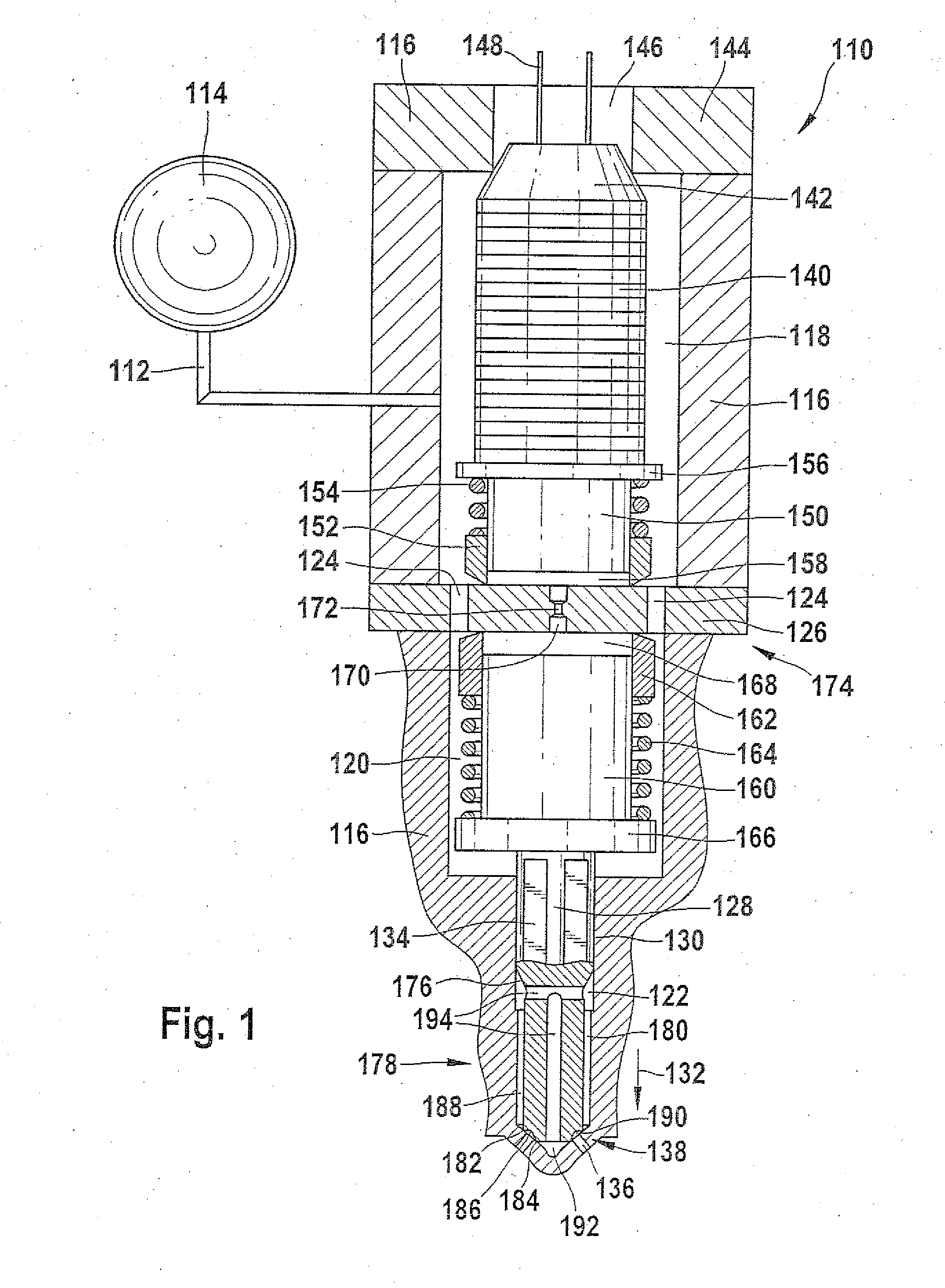
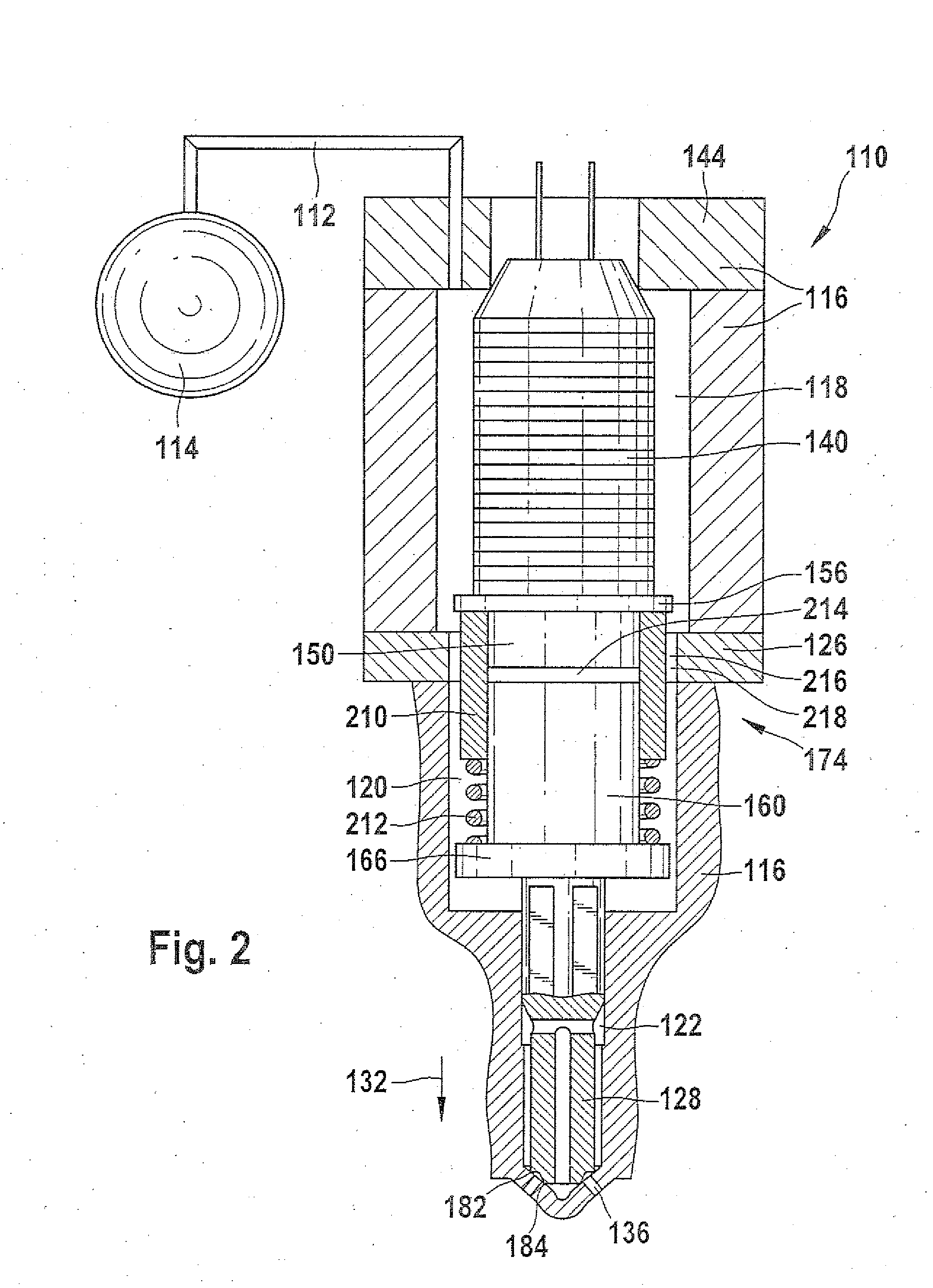
[0017]FIG. 1 shows a first, preferred exemplary embodiment of a fuel injector 110 for injecting fuel into a combustion chamber of an internal combustion engine. The fuel injector 110 communicates via a high-pressure line 112 with a pressure reservoir (common rail) 114. The fuel injector 110 also has an injector housing 116. The injector housing 116 has a high-pressure chamber 118, which is in communication with the pressure reservoir 114 via the high-pressure line 112 and is supplied with fuel that is under pressure. The injector housing 116 also has both a pressure chamber 120 and a nozzle chamber 122. The pressure chamber 120 is in communication with the high-pressure chamber 118 via fuel conduits 124, which are let into a partition 126 that divides the pressure chamber 120 from the high-pressure chamber 118. The fuel conduits 124 are embodied in this exemplary embodiment as cylindrical bores, which are made in the partition 126. Other designs of the fuel conduits are also conceiv...


PUM


Abstract

A fuel injector is supplied with fuel under pressure via a high-pressure source and has direct control of an injection valve member by a piezoelectric actuator via a hydraulic booster. The injection valve member of the fuel injector furthermore has a double seat and the injection valve member is provided with two sealing seats which subdivide a nozzle chamber of the fuel injector into three subchambers. When the injection valve member is closed, a first subchamber and a third are in fluidic communication with one another and are supplied with fuel. The second subchamber, which is in communication with injection openings, is conversely fluidically decoupled from the subchambers by the sealing seats. This proposed disposition, with a combination of direct needle control and a double seat of the injection valve member has the advantage that unthrottling of the fuel injector occurs at a very short injection valve member stroke. As a result, even short piezoelectric actuators can in particular be used.

Description

FIELD OF THE INVENTION [0001] The invention relates to a fuel injector for injecting fuel, delivered to the fuel injector via a high-pressure source, into a combustion chamber of an internal combustion engine. In particular, the invention relates to a fuel injector with a direct-controlled injection valve member with a double seat. PRIOR ART [0002] For supplying combustion chambers of self-igniting internal combustion engines with fuel, both pressure-controlled and stroke-controlled injection systems can be used. As the fuel injection systems, not only unit fuel injectors and pump-line-nozzle units but also reservoir injection systems are used. Reservoir injection systems (common rails) advantageously make it possible to adapt the inject pressure to the load and rpm of the engine. [0003] In the prior art, common rail injectors with piezoelectric actuators are known, in which a nozzle needle is controlled by way of the pressure in one or more control chambers. The pressure in this co...

Claims


Application Information

Patent Timeline
Patent Type & Authority Applications(United States)
IPC IPC(8): F02M51/06
CPCF02M51/0603F02M61/042F02M2200/704F02M2200/703F02M61/18
Inventor MAGEL, HANS-CHRISTOPH
Owner ROBERT BOSCH GMBH
Learn More