
Multifunction ignition device integrated with spark plug

a multi-functional, spark plug technology, applied in the direction of machines/engines, fuel injection with sensors, mechanical equipment, etc., can solve the problems of reducing the installation space of internal combustion engines, affecting the high efficiency combustion design of engines, and compact internal combustion engines, so as to simplify the ignition device and improve the ignition reliability

Inactive Publication Date: 2008-05-01
TOYO DENSO
View PDF14 Cites 42 Cited by
  • Summary
  • Abstract
  • Description
  • Claims
  • Application Information

AI Technical Summary

Benefits of technology

[0008] An object of the present invention is to provide a multifunction ignition device integrated with a spark plug for conserving space by integrating a spark plug, ignition coil, and fuel injection device in a single enclosure and for making a high fuel efficiency engine design possible and allowing spark plug electrode replacement, thereby reducing waste during plug maintenance.

Problems solved by technology

Major design problems have therefore arisen in reducing installation space for internal combustion engines, including making internal combustion engines more compact.
Conventional combustion devices of the independent ignition type are concentrated in the narrow range of spark plugs, ignition coils, and direct injection injectors, and hinder high efficiency combustion design for engines by reducing design freedom in the vicinity of the cylinder head.
However, a problem arises inasmuch as the ignition coil must be provided separately since the ignition coil is not housed within the case.
Although compact, this configuration has a disadvantage inasmuch as it does not have a fuel injection function, and a fuel injection device must be provided separately.
Furthermore, the devices disclosed in both of these patent documents have an integrated structure in which the spark plug can not be removed from the housing, thereby adversely affecting maintenance characteristics and causing needless waste because the other functional components, such as a fuel injection device that does not have durability problems, must be replaced when replacement of the device is necessary due to wear of the spark plug electrode.

Method used


Image

  • Multifunction ignition device integrated with spark plug
  • Multifunction ignition device integrated with spark plug
  • Multifunction ignition device integrated with spark plug

Examples


Embodiment Construction

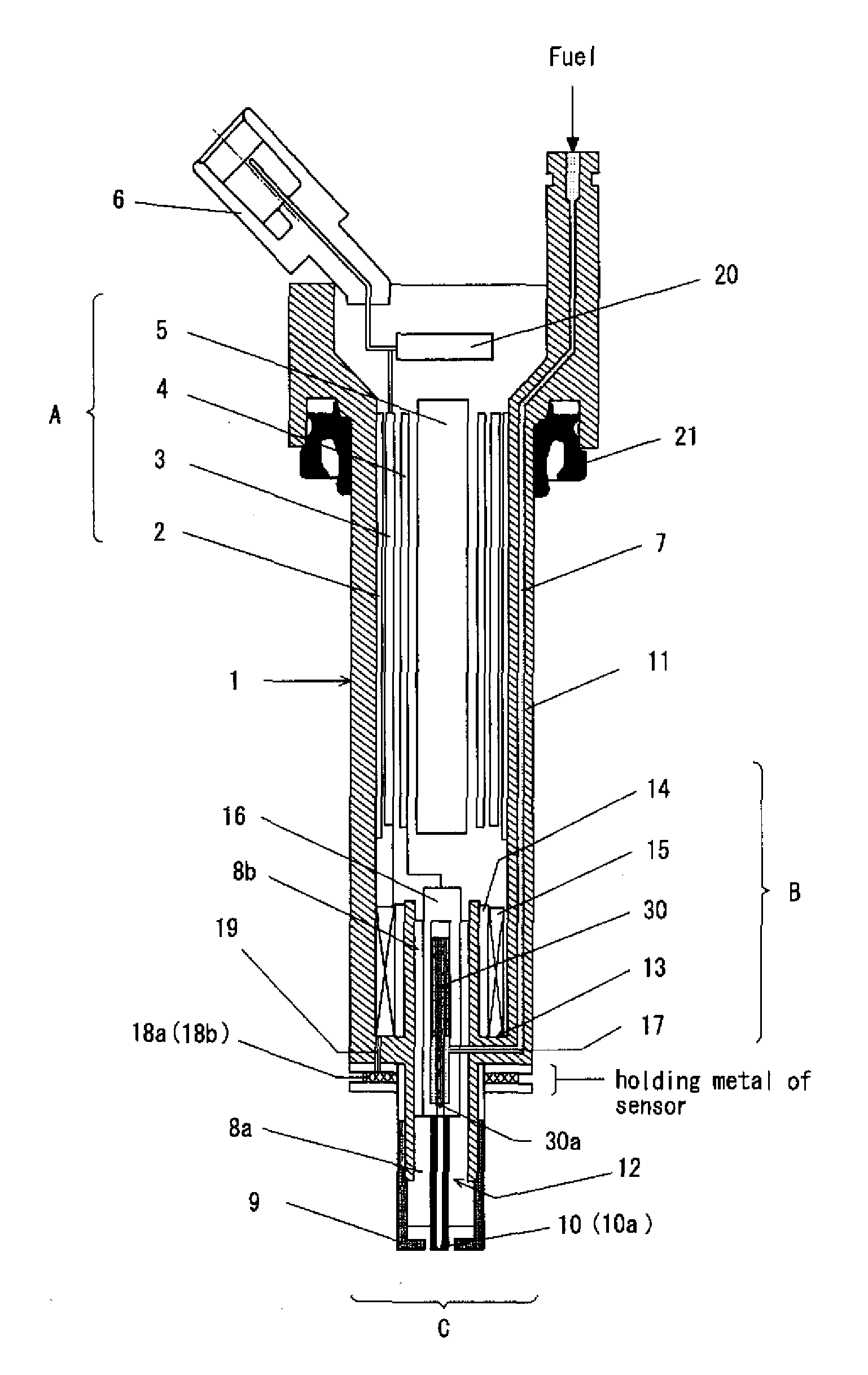
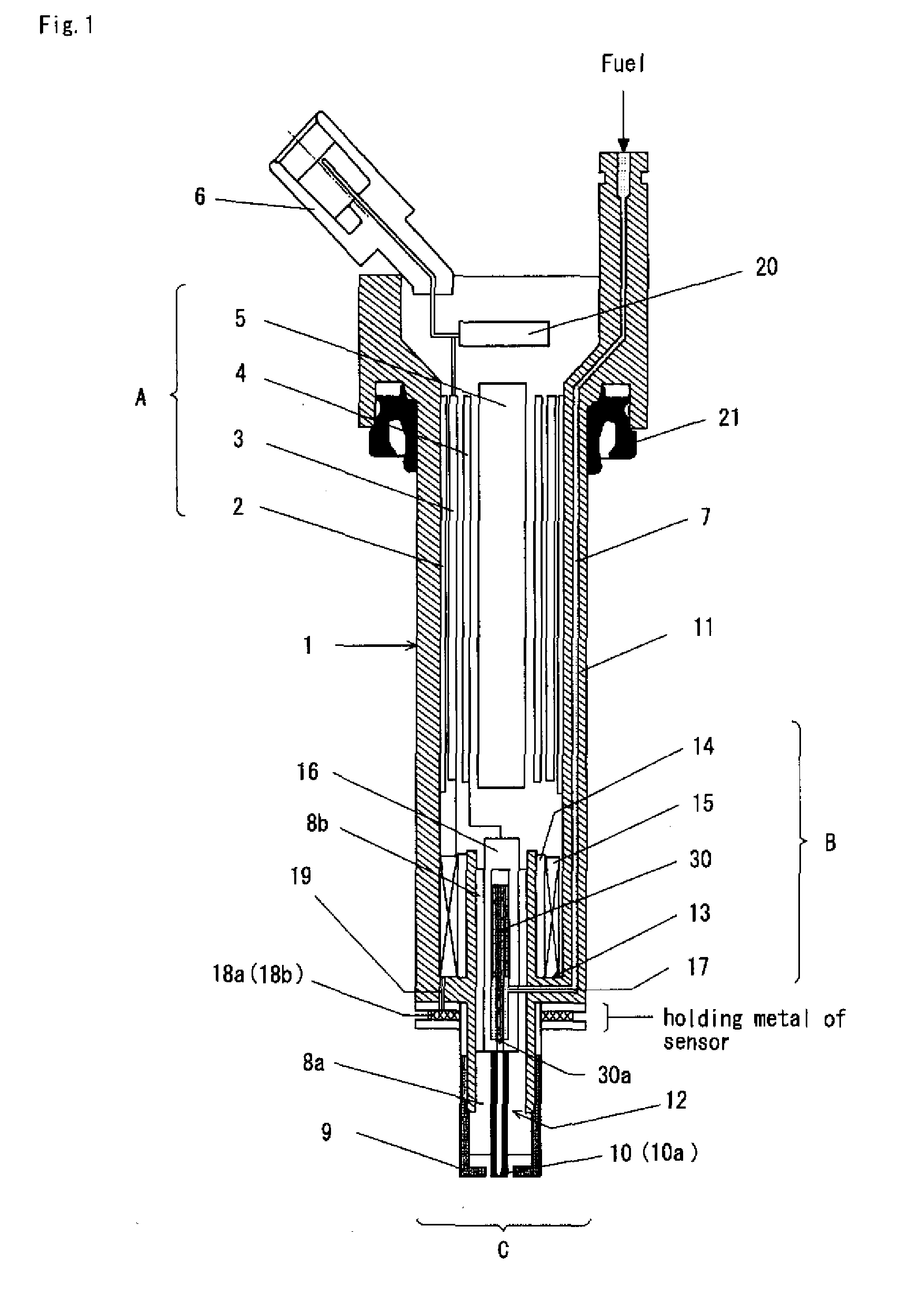
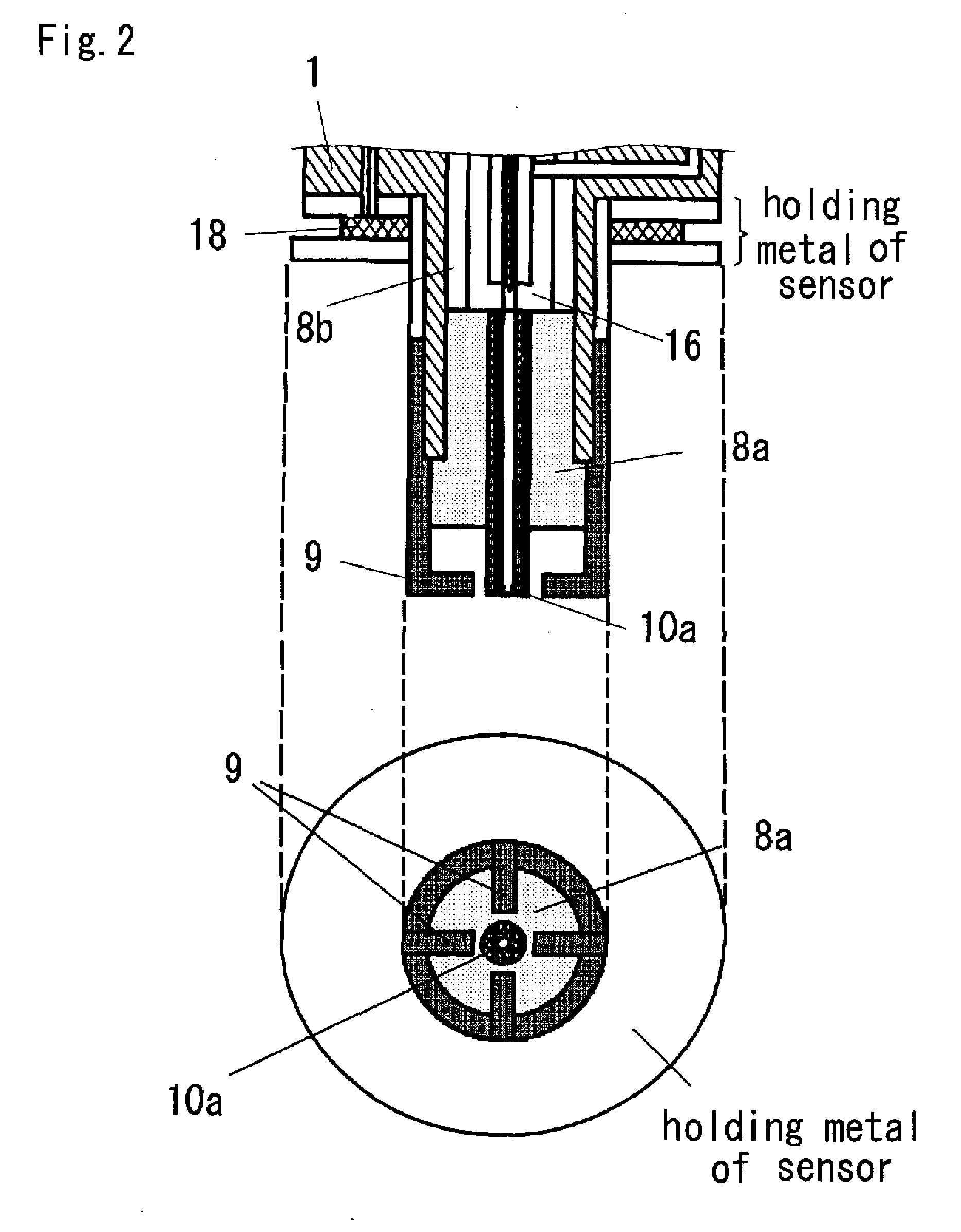
[0029]FIG. 1 shows a vertical section view of one embodiment of the multifunction ignition device with an integrated spark plug of the present invention. In this embodiment, an ignition coil part A is disposed in a top section of a cylindrical metal case 1, an electromagnetic fuel injection part B is disposed in a bottom section thereof, a center electrode 10a is disposed as a spark plug C combined with an injection nozzle in the bottom part thereof, and a plurality of ground electrodes 9 formed by multielectrodes are disposed so as to circumscribe the center electrode 10a. A combustion pressure sensor 18a or ionic current sensor 18b, which is sandwiched between two washers and fastened with a screw, is disposed on the outer wall of the bottom part 13 of the metal case 1.

[0030] The metal case 1 has a cylindrical shape so as to be directly insertable in the plug hole of the engine, and a fuel channel 7 disposed within the wall 11 of the metal case 1 communicates with the fuel inject...


PUM


Abstract

The object of the present invention is to provide a multifunction ignition device integrated with a spark plug for conserving space by integrating a spark plug, ignition coil, and fuel injection device in a single enclosure and for making a high fuel efficiency engine design possible and allowing spark plug electrode replacement, thereby reducing waste during plug maintenance. The multifunction ignition device of the present invention includes an ignition coil directly connected to a plug top of an internal combustion engine; the ignition coil, a fuel injection valve, and a fuel injection nozzle are housed in a single enclosure; and a center electrode and a ground electrode of the spark plug are removably mounted at the bottom end of the enclosure.

Description

BACKGROUND OF THE INVENTION [0001] 1. Field of the Invention [0002] The present invention relates to an ignition device directly mounted on the head cover of an engine of the independent ignition type among ignition devices for engines used in automobiles and the like. [0003] 2. Description of the Related Art [0004] Efforts have been made recently to effectively ensure the space within an engine room for mounting many electronic devices such as sensors around the engine in conjunction with providing increasingly high performance automobiles. Major design problems have therefore arisen in reducing installation space for internal combustion engines, including making internal combustion engines more compact. Conventional combustion devices of the independent ignition type are concentrated in the narrow range of spark plugs, ignition coils, and direct injection injectors, and hinder high efficiency combustion design for engines by reducing design freedom in the vicinity of the cylinder ...

Claims


Application Information

Patent Timeline
Patent Type & Authority Applications(United States)
IPC IPC(8): F02M57/06
CPCF02M51/005F02M57/06F02M2200/8053F02M2200/24F02M61/168
Inventor SAKAMAKI, MAKOTO
Owner TOYO DENSO
Learn More