
Air-conditioning installation and computer system

a computer system and air conditioning technology, applied in the field of air conditioning installation and computer system, can solve the problems of high driving cost of air conditioning installation, inability of air conditioning installation to show air conditioning ability, so as to achieve sufficient cooling and reduce power consumption

Inactive Publication Date: 2008-05-01
FUJITSU LTD
View PDF9 Cites 58 Cited by
  • Summary
  • Abstract
  • Description
  • Claims
  • Application Information

AI Technical Summary

Benefits of technology

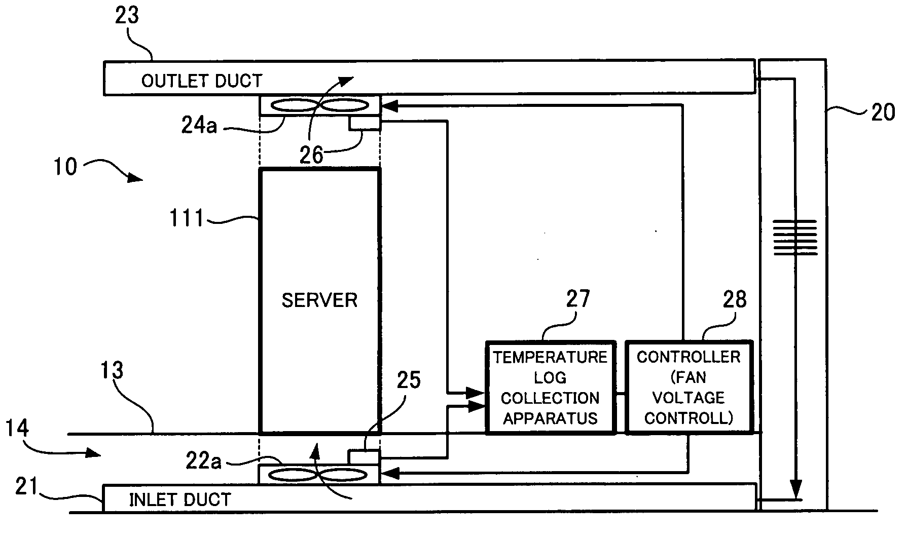
[0018]According to the present invention, the air conditioning installation has the inlet duct and can let a stream of air-conditioned cool air flow smoothly. In addition, there are disposed the inlet fans for the respective computer apparatuses at the positions corresponding to the inlets of the computer apparatuses. Thus, the air conditioning installation can cool each of computer apparatuses sufficiently.
[0023]In this case, further reduction in power consumption and more precise control for individual cooling of the computer apparatuses can be realized because a stream of the exhausted air is also controlled for each of the computer apparatuses.
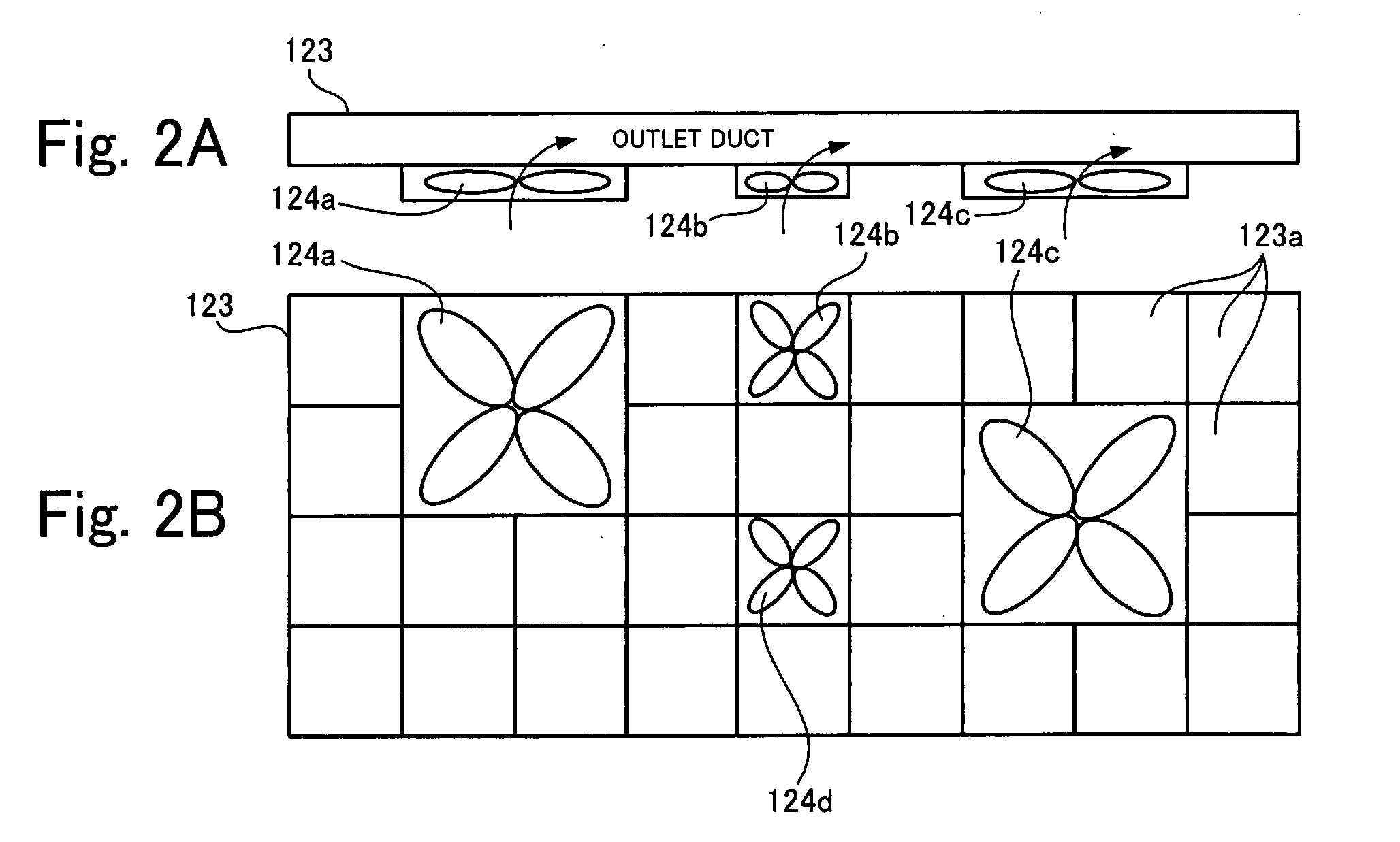
[0027]The above features make it possible to dispose the inlet fans at the desired position by combining the unit panels. As a result, options as to where the computer apparatuses are disposed in the room increase.
[0029]It is possible to use a rising stream of air which is induced by temperature increase by disposing the outlet duct near the ceiling. Moreover, it is also possible to dispose the outlet fans at the desired position by combining the unit panels. As a result, options for disposing the computer apparatuses in the room increase.
[0035]Even in the case where only a single computer apparatus is installed, heating value changes with time depending on how the computer apparatus is driven. If the structure is employed in which a rotational speed of each fan is individually controlled based on the temperature measurement result by the temperature sensors for the outlet fans or both the outlet fans and the inlet fans, it is possible to individually optimize a flow of cool air flowing through each computer apparatus with time according to each heating value of the computer apparatuses which changes with time. Therefore, more preferable air conditioning installation is realized in terms of lower power consumption and driving cost.
[0044]As described above, the present invention can realize lower power consumption and perform sufficient cooling for each computer apparatus.

Problems solved by technology

As a result, in the case of a direct blow into the computer room, it is sometimes impossible for the air conditioning installation to show its air-conditioning ability as designed and carry out necessary cooling because of difficulty in even air-conditioning of the whole room and large differences in the temperature depending on locations in the computer room.
Also, in the case of a blow into a space under a free access floor, it is sometimes impossible for the air conditioning installation to show its air-conditioning ability as designed because many cables ordinarily disposed in the space prevent smooth flowing of a stream of cool air.
But in this case, higher driving cost for the air conditioning installation is required in addition to significantly increased power consumption.
Therefore, this choice is disadvantageous in terms of lower power consumption and driving cost.
Moreover, each of computer apparatuses has generally a different heating value, and it is impossible to control cooling ability of the above-described air conditioning installation for the respective computer apparatuses.
In the air-conditioning installation, air-conditioned cool air is smoothly blown into a computer room because there is installed a duct under a floor of the computer room, but it is impossible to individually control its cooling ability for each computer apparatus.
But, in the case in which there are several computer apparatuses in the computer room, it is impossible to individually control its cooling ability for each computer apparatus.
But Japanese Patent Application Publication No. 2005-503529 does not disclose air-conditioning a whole of a computer room.

Method used


Image

  • Air-conditioning installation and computer system
  • Air-conditioning installation and computer system
  • Air-conditioning installation and computer system

Examples


Embodiment Construction

[0050]Embodiment(s) of the present invention will be described below.

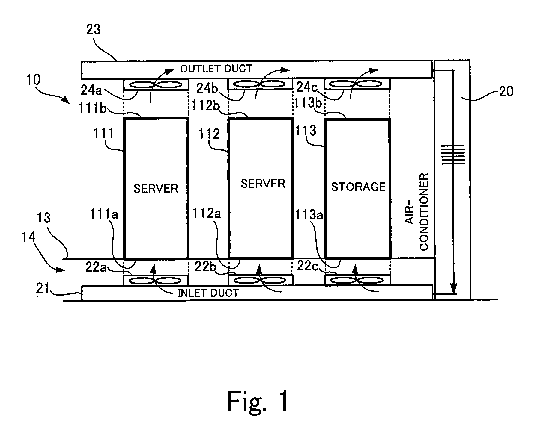
[0051]FIG. 1 is a schematic diagram showing a computer room where computer apparatuses are installed, and an air conditioning installation which air-conditions the computer room.

[0052]In a computer room 10 shown in FIG. 1, there are disposed servers 111, 112 and storage 113 each of which is a kind of large computer.

[0053]Also, there is respectively provided an inlet duct 21 near a floor of the computer room 10 through which air is sent from an air-conditioner 20. In addition, inlet fans 22a, 22b, 22c are disposed on the inlet duct 21 at the respective positions corresponding to the servers 111, 112 and the storage 113 which are subjects to be cooled.

[0054]The upper surface of the inlet duct 21 is made of a combination of unit panels. Therefore, it is possible to dispose the inlet fans at desired positions by combining the unit panels. As a result, options as to where the computer apparatuses are disposed in the roo...


PUM


Abstract

An air conditioning installation cools computer apparatuses by air-conditioning a room where the computer apparatuses are installed. The air conditioning installation includes:(a) an inlet duct for making air flow into the room; (b) an air-conditioner which sends air into the inlet duct, and (c) inlet fans for the respective computer apparatuses to be cooled. The inlet fans are disposed at positions corresponding to inlets of the computer apparatuses installed in the room, and send air flown through the inlet duct into the room such that the air flows toward the inlets of the computer apparatuses.

Description

BACKGROUND OF THE INVENTION[0001]1. Field of the Invention[0002]The present invention relates to an air conditioning installation which air-conditions a room where computer apparatuses for data processing are installed in order to cool the computer apparatuses, and a computer system which has computer apparatuses and an air-conditioning installation.[0003]2. Description of the Related Art[0004]Conventionally, there has been employed a method in which a room where plural large computer apparatuses, for example, servers and storages are installed is air-conditioned so as to cool these computer apparatuses.[0005]When an air conditioning installation for the computer room is designed, air-conditioning ability is estimated based on a total heating value of the computer apparatuses installed in the computer room. Then, an amount of cool air required for necessary air-conditioning ability is blown directly into the computer room or is blown into a space under a free access floor for cable ...

Claims


Application Information

Patent Timeline
IPC IPC(8): F25D23/12F24F11/76
CPCH05K7/20745F24F7/08F24F7/10F24F11/0001F24F11/77F24F2110/10
Inventor YAMAOKA, NOBUYOSHI
Owner FUJITSU LTD
Learn More